


Electric Control Unit for Exhaust Brake
Page 88
If you've noticed an error in this article please click here to report it so we can fix it.
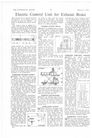
A N electrical unit to provide automatic operation of an exhaust brake is described in Ratent No. 804,813. (R. Haller, 51 Brauerstrasse, Zurich, Switzerland.) The exhaust brake is applied by a throttll valve located in the exhaust pipe and this is worked by the electric control unit shown in the drawing. A reversible electric motor (1) energized from the vehicle batteries drives a freely mounted tubular member (2). In the end of the tube is a nut (3) which, when rotated, pulls the screwed rod (4) in or out provided the rod is held from turning. This actuates another rod (5) to operate the exhaust brake valve.
As the electric motor is still running when the valve reaches its limit of movement, the unit incorporates a release mechanism in the form of a coiled-spring clutch (6) which holds the rod from rotation, but, at the end of the stroke, emerges from the slot (7) and lets the rod run freely.
The patent gives full details of the electric control contacts which are attached to both the clutch and the accelerator pedals, the aim being to ensure automatic operation in all circumstances.
SIMPLIFIED IGNITION SYSTEM
PATENT No. 805,356 describes an ignition system in which the high voltage for the sparking-plug is created in a novel manner. (McCulloch Motors Corp., 6101 West Century Boulevard, Los Angeles, California, U.S.A.)
If the two plates of a condenser are moved apart, its capacitance is reduced. If it is charged first, and then has its plates separated, the total energy must remain constant. This means that the reduced capacitance results in a higher voltage across the plates.
The drawing illustrates diagrammatically how the scheme is put into practice. A comparatively low-voltage battery (l) is connected between a fixed condenser plate (2) and the sparking plug terminal (3). A high value resistance (4) is shunted across the plug points. The movable condenser plate (5) is worked by a snail cam (6) giving a stoic rise and a sudden fall under spring force.
During the idle period, the battery charges the condenser through the resistance. When the plates are moved apart, a high voltage is generated and the current flows back through the battery and across the plug points; the resistance having too high a value to affect the sequence.
The patent states that
no energy is taken from the battery because of the back-flow. The energy for the spark comes from the mechanical input to the cam. The patent suggests the use of a radioactive battery.
COMMER LIFTING TRUCK
PATENT No. 804,890 refers to vehicle bodies capable of being raised bodily. Such vehicles arc particularly suitable for loading and unloading goods from aircraft. (A. Binns and Commer Cars, Ltd., Biscot Road, Luton, Beds.)
The vehicle, shown in the drawing, has a conventional four wheeled chassis and cab. The body, however, is attached to the frame by pairs of scissor-like linkages (1). The lifting force is provided by a pair of hydraulic rams (2) interposed between a cross-member on the chassis and a cross-bar on the scissor links.
A feature of the invention is the provision of a hinged forward platform (3). This normally lies in a vertical position behind the cab, but when extended gives extra loading space over the cab.
The action is quite automatic, the platform being guided by rollers (4) which engage with curved channel members (5). Once the platform is extended, it is supported by hinged stays (6).
STEERING FOR TRAILERS DATENT No. 804,836 comes from E.
Bobard, Rue de Reon, Beaune (Cote d'Or), France and discloses a scheme for steering both the front and rear wheels of a trailer so that they follow a common turning circle.
COMBUSTION SYSTEM NAODIFICATIONS to the shape of oilLvi engine combustion chambers form
the subject patent No. 805,104. The layout shown specifies a conical outline for the combustion chamber; this is said not only to give better results through more efficient mixing of the fuel and air in the chamber, but is also easier to machine than the spherical form often used (Ricardo and Co. Engineers (1927i Ltd., 27a Ashley Place, London, S.W.1.
As shown in the drawing, the chamber is octagonal in elevation, made up of two partial cones and a cylindrical portion in the middle bounded by flat surfaces at top and bottom. The connecting passage (1) to the cylinder is a circumferential slot breaking into one of the coned surfaces. The injector (2) breaks into the other at a point diametrically opposite, so that it delivers its fuel charge into a swirling air stream.
The lower part of the chamber is formed as a " hot plug (3) which is spaced away from its surroundings except on its clamping faces. This enables it to reach a much higher temperature than the surrounding metal.
IMPROVED INJECTION NOZZLES DATENT No. 804,723 describes improvements in the design of inject ion nozzles. The advantages claimed are quick and effective return of the valve member and elimination of dribble. (C.A.V., Ltd., Warple Way, London, W.3, and Ricardo and Co. Engineers (1927), Ltd., Bridge Works, Shoreham-by-Sea, Sussex.) Referring to the drawing, the valve (1) has an enlarged end comprising a conical seating (2) and a short parallel land (3) on its tip; this land closely fits its surrounding bore. A side orifice (4) connects the exterior to a point just under the conical scat.
When the pressure pulse arrives from the pump, the fuel passes through ports (5), the space (6) and helical grooves (7) to reach the space above the conical seat. As soon as the pressure overcomes the spring, the valve unseats and delivers a small pilot jet of fuel through the side orifice. Full flow occurs only when the parallel land at the bottom of t he valve emerges from its
bore. The valve is forced back onto its seat by a combination of spring and combustion pressure. This action gives rapid cut-off and thus eliminates dribble.
HARDENING VALVE SEATS
MOST cast irons will harden if chilled and patent No. 804,924 suggests a method of doing this in situ for the valve seats in a cast-iron cylinder head. (S.A. de Vehicules Industriels et &Equipments Mecaniques, 41 Avenue Hoch, Paris