


Patents Completed.
Page 30
If you've noticed an error in this article please click here to report it so we can fix it.
Complete specifications of the following patents will be sent to any address in the by the Sales Branch, Patent Office, Holborn, W.C., upon receipt of eightpence United Kingdom per copy.
The Manufacture of Solid Tires.
C. Challiner, No. 21,891, dated 26th September, 1812, Cognate Application No. 22,690, dated 5th October, 1912.— This specification describes an unproved construction of solid rubber tires such as are fitted on heavy motor vehicles. Tin.
tire has hitherto been mounted on a band provided with dovetail recesses ; these are somewhat expensive to produce. According to the present invention, two or more perforated metal bands or dovetail hoops are assembled together, to form a single band in which lightness and strength are combined. A large number of modifications are described and illustrated in the specification, but the common feature of them all is the use of a band consisting of two or more perforated metal bands or plain and perforated bands which are secured together (by shrinking or riveting), and which may have their adjacent edges countersunk if desired.
Improved Rotary Valves.
J. Rothchild and J. B. Jarvis, No. 179, dated 2nd January, 1912.—The valve described in this specification comprises a continuously-rotating cylindrical valve arranged within a valve chamber at the top of the cylinder. This chamber is open on its under side to the cylinder aud has a port along the top connected with the induction pipe ; it is also open at one end and communicates with the exhaust. Within the valve chamber there is provided a sleeve in which a series of parallel axial ports is equally spaced, and this member is continuously rotated so as to cause these ports to register in
turn with the cylinder and with the iidet ports. They also provide communication with the exhaust port which is separated from the inlet port by an independent member mounted inside the
cylindrical valve so as to divide the interior into two portions one of which communicates with the exhaust, while the other communicates with the inlet. This inner member is arranged to be rotated and set in a variety of positions according to the requirements at the time. Passages are provided in it by which compressed air can be conducted to the engine cylinders for starling; the retating valve controls these passages and puts the .ylittder alternately in communication with the compressed-air supply and also with the exhaust. When the engine has reached a comparatively high speed, the internal valve is ad. jueted so that the rotation of the sleeve puts the cylinder into communication alternately with the ordinary inlet port and exhaust port as required for normal working. Various details, such as the arrangement for keepinF the main valve in contact with its seating are described and illustrated at some length in the specifleati
A Hydraulic Gear.
Soc. Anon. des Automobiles Delaunay and Belleville, No. 15,863, dated 6th July, 1912, Patent of Addition to No. 1072, of 1911.—This specification describes an improved form of the hydraulic-transmission apparatus described in Patent. No. 1072, of 1911. The object of this invention is to reduce the number of bearings, and also to eliminate the somewhat considerable loss of power due to the friction of the long sleeve. The driving shaft extends through the casing of the hydraulic gear beside the two sets of pumps. A pinion at the one end meshes with a gear wheel on the pump spindle, and operates tho driving pumps. A similar gear wheel at the other end meshes on a pinion loose on the driven shaft near the cardan joint, and a clutch is provided by which this second pinion can be clutched to the shaft. One of the features of this invention consists in the arrangement of the clutch which comprises a sleeve provided with two rings of claws. In one position, the loose pinion is clutched to the driven shaft, and the drive is transmitted through the hydraulic reducing gear. In the other position the driving shaft is clutched direct to the driven shaft. Multiple Boring Bar.
H. Austin, No. 117, dated 2nd January, 1912.—A useful tool for facing up the opposite sides of the crankshaft bearing-blocks of an internal-combustion engine, is described in this specification. The tool consists of a hollow cylinder slotted through its diameter at intervals to receive the cutting tools. A semicircular bar extends right through the cylinder, and this has inclined key-ways cut in it to receive the keys by which the cutting tools are held in position. It will be seen that, as this semi-circular bar is pushed backwards and forwards, the cutting tools will be projected and withdrawn so that the tools can be gradually fed out while truing up the blocks. It can then be withdrawn into the bar, and the whole tool removed.
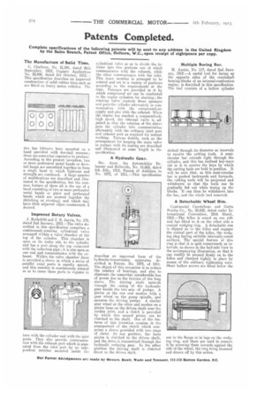
A Detachable 'Wheel Rim.
Continental Caontchouc and Gude Percha Co., No. 23,632, dated under International Convention, 25th March, 1912.—The felloe is coned on one side and has fitted to it on the other side a -conical wedging ring. A detachable rim is slipped on to the felloe and engages the conical part of the felloe, the wedging ring having suitable internally-coned surfaces. The special feature of this ring is that it is split transversely at integvals, as shown in the half-side view in the accompanying illustration, so that it can readily be pressed firmly on to the felloe and clamped tightly in place by means of the ordinary tightening nuts. Short hollow screws are fitted below the nut in the flange or in lugs on the wedging ring, and these are used to remove it -by screwing them inwards against the side of the wheel, the ring being loosened and drawn off by this action.