 1
1 2
2 3
3 4
4 5
5 6
6 7
7 8
8 9
9 10
10 11
11 12
12 13
13 14
14 15
15 16
16 17
17 18
18 19
19 20
20 21
21 22
22 23
23 24
24 25
25 26
26 27
27 28
28 29
29 30
30 31
31 32
32 33
33 34
34 35
35 36
36 37
37 38
38 39
39 40
40 41
41 42
42 43
43 44
44 45
45 46
46 47
47 48
48 49
49 50
50 51
51 52
52 53
53 54
54 55
55 56
56 57
57 58
58 59
59 60
60 61
61 62
62 63
63 64
64 65
65 66
66 67
67 68
68 69
69 70
70 71
71 72
72 73
73 74
74 75
75 76
76 77
77 78
78 79
79 80
80 81
81 82
82 83
83 84
84 85
85 86
86 87
87 88
88 89
89 90
90 91
91 92
92 93
93 94
94 95
95 96
96 97
97 98
98 99
99 100
100 101
101 102
102 103
103 104
104 105
105 106
106 107
107 108
108 109
109 110
110 111
111 112
112 113
113 114
114 115
115 116
116 117
117 118
118 119
119 120
120 121
121 122
122 123
123 124
124 125
125 126
126 127
127 128
128 129
129 130
130 131
131 132
132 133
133 134
134 135
135 136
136 137
137 138
138 139
139 140
140 141
141 142
142 143
143 144
144 145
145 146
146 147
147 148
148 149
149 150
150 151
151 152
152 153
153 154
154 155
155 156
156 157
157 158
158 159
159 160
160 161
161 162
162 163
163 164
164 165
165 166
166 167
167 168
168 The right angle on tipping gear
Page 80
Page 81
Page 82
If you've noticed an error in this article please click here to report it so we can fix it.
overhaul by R cater, p. sBE
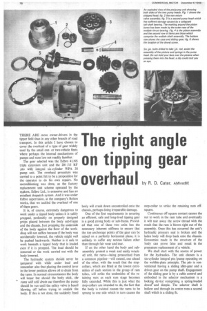
THERE ARE more owner-drivers in the tipper field than in any other branch of road transport. In this article I have chosen to cover the overhaul of a type of gear widely used by the small oneor two-vehicle fleets where perhaps the internal mechanisms of pumps and rams'are not readily familiar.
The gear selected was the Edbro 4LNS triple extension unit and the 201 /15 RF pto with integral six-cylinder WPA 38 pump unit. The overhaul procedure was carried to a point felt to be a proposition for the operator to do his own repairs. No reconditioning was done, as the factory replacement unit scheme operated by the makers, &limo Ltd., is extensive and has an exCellent despatch system. And it was under Edbro supervision, at the company's Bolton works, that we tackled the overhaul of one of these gears.
It is, of course, extremely dangerous to work under a tipped body unless it is safely propped, preferably on properly designed props placed between the body sub-frame and the chassis. Just propping the underside of the body against the floor of the workshop will not suffice because if the body was accidentally lowered, the vehicle might well be pushed backwards. Neither is it safe to work beneath a tipped body that is loaded even if it is propped. The load should be removed or the work carried out with the body lowered.
The hydraulic system should never be tampered with while under load and remember also that placing the control lever in the lower position allows oil to drain from the rams. In normal circumstances the body will lower but should the body stick, the rams will still drain out therefore the pump should be run until the safety valve is heard blowing off before trying to unstick the body. If this is not done, the suddenly freed
body will crash down uncontrolled onto the chassis, perhaps doing irreparable damage.
One of the first requirements in securing an efficient, safe and long-lived tipping gear is a good strong body or sub-frame. Provided that one of these two units has the necessary inherent stiffness to ensure that the top anchorage points of the gear can be raised on a perfectly horizontal plane, it is unlikely to suffer any serious failure other than through fair wear and tear.
If on the other hand the body and subassembly present a weak and easily wracked unit, the rams—being pressurized from a common pipeline—will extend, one ahead of the other, with the result that the stopcollars, which are fitted at the lowest extremities of each section in the group of rain tubes, will strike the undersides of the retaining nuts as each ram stage becomes fully extended. While this is just what the stop-collars are intended to do, the fact that the body is twisted causes the rams to be sprung to one side which in turn causes the stop-collar to strike the retaining nuts offsquare.
Continuous off-square contact causes the nut to work in the ram tube and eventually it will tear away the screw thread with the result that the ram is blown right out of the assembly. Once this has occurred the unit's hydraulic pressure seal is broken and the laden body will drop back onto the chassis. Economies made in the structure of the body can prove false and result in the premature replacement of a vehicle.
We shall start with the source of power for the hydraulics. The unit chosen is a six-cylinder integral pto /pump operating on the wobble-plate principle. The pto is conventional having a sliding idler-gear and a driven gear on the pump shaft. Engagement of the sliding gear is by a cable control and embodied in the selector mechanism is a lockinE device comprising a spring-loaded dowel and dimple. The selector shaft is hollow and through its centre runs a second shaft which is a sliding fit.
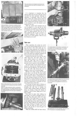
It is important to recognize that the selector shaft will not move until this central trip-shaft has been operated. Although its operation is automatic when the control cable is fitted, this locking device should be extended on all occasions when the selector shaft is being moved during overhaul. Force is not required to move the selector and it should not be used.
With the control unit removed, the pto can be gripped in a vice and the six bolts securing the two sections of the casing can be slackened off. The casings will be forced apart by spring pressure and two of the bolts should be left in situ to prevent uncontrolled explosion. With this done the casing can be held together while the last few threads are run off.
Take care
When separating the casing be careful not to let the spring-loaded pistons fly out as the non-return valve balls might get lost. With the casing separated the condition of the bearings supporting the cam spindle will be evident. Should the ball-race at the tail end of the shaft have collapsed, damage will have occurred to the cylinder casting.
Examine the face-cam race and the taper roller thrust-race. The taper roller, it appears, seldom requires any attention. If it does, the roller cage must be split and removed before a drawer can be applied to the inner race to remove it from the shaft.
The pump shaft can be released from the casing by removing the bearing cap from the pto end and applying a few sharp blows to a soft drift. The thrust-race can be wedged or drawn off its locating spigot.
Between the pump casing and the pto casing there is an oil seal. On some earlier pumps the shaft and a loose distance-piece were produced without a fitting-lead to assist their passage through the seal. This has been known to cause damage to the seal by turning up its retaining lip and allowing the transfer of lubricating or hydraulic oil from one compartment to the other.
If your gear oil shows signs of dilution or your hydraulics signs of contamination it is probably this seat that is causing the trouble. When refitting shafts and distance pieces not having a lead, this should be applied. A lead of about 30deg and 0.125in. long is ample.
Care must be taken when refitting the main shaft to see that no damage is done to the seal. One other point which will make the fitting of the shaft easier is to see that the driven gear, which is a keyed sliding fit on the shaft, does in fact slide over the shaft and key before offering the assembly up to the casing. Having to struggle to force the gear onto the shaft can also result in damage to the oil seal, so ease the gear's fit before assembling.
When the wobble shaft has been relocat ed in the housing the tail bearing is fitted, not forgetting the distance washer which is carried between the spigot-shoulder and the inner race of the bearing. Re-fit the end-cap with a new gasket and turn your attention to the idler shaft and gear assembly for pto. When the shaft is fitted it should be inserted from the pto end of the casing and as it is a tight push fit in order to form an adequate oil seal between itself and the casting, it must be hammered home with a soft copper or lead mallet. Because this method of assembly is used it is important always to remove this shaft by applying a drift to its pump end, driving it out in the opposite direction to which it was inserted. During assembly there is a likelihood of slight mushrooming of the shaft end and to drive it right through from the pto end might cause opening out of the holes in the casting.
Drive the idler shaft right home until the grub-screw dowel can be inserted in the joint-flange face and screwed right home. The gear selector unit can now be mounted on the casing and tested to ensure that it is operating correctly, remembering the locking device mentioned earlier.
Turning to the pump end, having ascertained that the casting is in good condition, that is to say that none of the cylinder bores is scored or badly worn, this can now be reassembled with any new parts that might be required. The makers recommend that new piston assemblies be used because a failure caused through tired materials can result in complete wrecking of the pump unit.
Assembly knack
Remember that the open end of the piston is the pressure side of the unit and when the piston sub-assembly, comprising the piston, a non-return ball, a plastics distance piece and spring, has been placed inside the piston in that order and then inserted into the cylinder, there will be a tendency for the spring to force the piston out of the casing. An assembly knack which factory engineers have developed is to take six kin. diameter by 3in. bolts and drill through the shank with a kht. diameter drill in a position which ranges level with the piston feed-holes when the springs are fully compressed. As each piston assembly is inserted in the casing a bolt is passed through the adjacent bolt hole and a piece of kin. diameter rod is in turn passed through the bolt and into the feed hole in the piston so retaining the compression spring while the remainder of the piston units are assembled.
The paper sealing gasket is then placed over the extending shanks of the drilled bolts, and after placing the ball cage and outer race of the thrust bearing in situ the pump head is fitted to the pto casing using the drilled bolts as a locating guide. It will be possible to close the gap between the two castings sufficiently to allow the original securing bolts to be substituted for those used to secure the piston assemblies after these have been removed one by one. As they are removed the pistons will extend from the cylinders and their thrust-ends will come into contact with the outer race of the thrust bearing. The retainers should be removed from diametrically opposite positions so that the casing can be held square as the securing bolts are inserted and then, when all these have been fitted, the case must be pulled down evenly all round.
Essential
It is essential when assembling the piston units to ascertain that the valve balls are free to move about inside the piston when the spring and retaining pad are in situ. Should they not be free it will be impossible to prime the pump.
In the delivery end of the pump casing is a two-piece non-return valve body which is ported to each cylinder and sealed on the piston's return stroke by yet another ball valve. The function of this chamber is to channel the pressurized fluid into a common passage as each piston in turn completes its pressure stroke, the non-return valves sealing the cylinder on the return stroke and causing the ball valve in the charging end of the piston to lift off its seat and so re-prime the cylinder.
It is vitally important that the correct size of valve ball is used in this assembly for any failure to lift off their seats sufficiently as the pistons charge the pump head will cause a hydraulic which will burst the head of the pump. To check that all is well in this direction place the balls in situ in the bottom half of the valve chamber and place the top half in position, hold the two halves together and check that the balls are free in the casing.
When the non-return valve seat is fitted into the pump head particular attention must be paid to the alignment of the dowels and holes which ensure that the porting from the cylinders and the holes in the valve cylinder are clear. A rubber 0-ring is fitted between the back nut And the casing of this unit and should any leakage of hydraulic fluid occur from this point, it is this that will be at fault. Remember that when dismantling this valve, once the end nut is removed there is nothing securing the balls inside and arrangements should be made to catch these as they fall from the body. This is particularly so if attention is given to the valve while the pump is fitted on a vehicle. The back nut is secured by a steel locking washer fixed by three kin. bolts. This is purely and simply a locking washer and has no sealing properties. It is therefore of no use tightening the securing bolts in an attempt to cure leaks, only replacement of the 0-ring can achieve this.
With regard to the power source for the tipping gear it remains but to ensure that all hydraulic joints are tight and leak free. Remember that bad joints on the feed side of the pump leading from the oil reservoir will cause air locking and stop the unit operating correctly, while leaks on the pressure side will prove messy and costly if not avoided.
Let us now turn to the ram assembly. The twin ram unit is mounted in an integral tank-come-support assembly and oil is fed to the base rams from a common pipeline. It follows therefore that ' provided the resistance to both rams is identical, when a given pressure is applied, both will extend simultaneously.
Reasons for this not being so are that either the rams are partially ceased or binding or that the imposed load at their top end is uneven. Binding can be caused either by damaged stop-collars which have been mushroomed by continuous heavy contact with the gland nuts of the consecutive units or where a ram tube has become distorted and will not therefore run through the gland nuts easily Overhaul of the rams is a simple and straightforward operation, the point particularly to watch for being the above-mentioned mushrooming of stop-collars and avoiding damage to the new pressure washers when these are passed through the threaded portion of the ram tubes. Edbro Ltd. produces a set of inserting sleeves for this purpose and these should be well worth their cost.
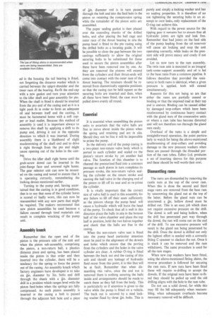
Dismantling rams
The rams are dismantled by removing the castle nuts at the top of the cover ram. When this is done the second and third stage rams are removed from the base ram by unscrewing the gland nut at the top of the latter. Before the gland nuts can be unscrewed a 4n. hollow dowel must be drilled out. This is an easy job which does not require excessive pressure on the drill. The dowel is soft and being hollow, when the drill has penetrated part way through the dowel, the rest will come out on the end of the drill. To use excessive pressure will result in the gland nut being penetrated by the drill. Once the dowel is drilled out only the lightest effort is needed with a correctly fitting C-spanner to slacken the nut. Once it is slack it can be removed and the ram withdrawn. The same procedure is used for all the ram stages.
When new cup washers have been fitted, using the above-mentioned fitting shims, the reverse procedure is followed for securing the ram nuts. If new nuts have been fitted these will require re-drilling to accept the dowels. If the original nuts have been re-fitted they should be pulled up until the old drilling aligns with the hole in the ram tube.
Do not use a solid dowel, for while this may fill the bill adequately when reassembling, when subsequent overhauls become necessary removal will be difficult.