


Selective Steering for All Wheels,
Page 48
If you've noticed an error in this article please click here to report it so we can fix it.
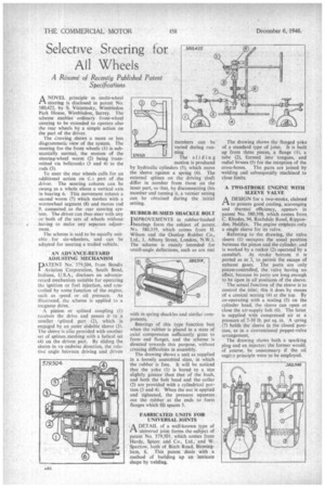
A R esume of Recently Published Patent Specifications ANOVEL principle in multi-wheel steering is disclosed in patent No. 580,422, by S. Viazemsky, Wimbledon Park House, Wimbledon, Surrey. The scheme .enables ordinary front-wheel steering to be extended to operate also the rear wheels by a simple action on the part of the driver.
The drawing shows a more or less diagrammatic view of the system. The steering for the front wheels (1) is substantially normal, the motion of the steering-wheel worm (2) being transmitted via belleranks (3 and 4) to the rods (5).
To steer the rear wheels calls for an
additional action on t part of the driver. The steering column can be swung as a whole about a vertical axis in bearing 6. This movement rotates a second worm (7) which meshes with a wormwheel segment (8) and moves rod 9, connected. to the rear steering sys. tern. The driver can thus steer with any or both of the sets of wheels without
having to make any separate adjust . rnent.
The scheme is said to be equally suitable for six-wheelers, and can be adapted for steering a trailed vehicle.
AN ADVANCE-RETARD ADJUSTING MECHANISM DATENT No: 579,504, from Bendix Aviation Corporation, South Bend, Indiana, U.S.A., discloses an advanceretard mechanism suitable for operating she ignition or fuel injection, and controlled by some function of the engine, such as speed or oil pressure. As illustrated, the scheme is applied to a magneto drive.
A pinion, or splined coupling (1) receives the drive and passes it to a smaller L.plined part (2), which is engaged by an outer slidable sleeve (3). The sleeve is ago provided with another set of splines meshing with a helical set (4) on the driven part. By sliding the s cave in an endwise direction, the relative angle between driving and driven members can be varied during running.
The sliding motion is produced by hydraulic cylinders (5), which move the sleeve against a spring (6). The external ,plines on the driving shaft differ in number from those on the inner part, so that, by disconnecting this member and turning it, a vernier setting can be obtained during the initial setting.
RUBBER-BUSHED SHACKLE BOLT IMPROVEMENTS in rubber-bushed 'bearings form the subject of patent Na. 580,319, which comes from H. Wilson and the -Dunlop Rubber Co., Ltd., 1, Albany Street, London, N.W.1. The scheme is mainly intended for small-angle deflections, such as are met with in spring shackles and similar components, Bearings of this type function best when the rubber is placed in a state of axial compression sufficiently great to form end flanges, and the scheme is directed towards this purpose, without creating difficulties in assembly.
The drawing shows a unit as supplied in a loosely assembled state, in which the rubber is free. It will be noticed that the yoke (1) is bored to a size slightly greater than that of the bush, and both the bolt head and the collar (2) are provided with a cylindrical portion (3 and 4). When the nut is applied and tightened, the pressure squeezes out the rubber at the ends to form flanges which fill spaces 5.
FABRICATED UNITS FOR UNIVERSAL JOINTS
-AL—% DETAIL of a well-known type of
universal joint forms the subject of patent No. 579,501, which comes from Hardy, Spicer and Co., Ltd., and W. Sparrow, both of Birch Road, Birmingham, 6. This patent deals with a method of building up an intricate shape by welding. The drawing shows the flanged yoke of a standard type of joint. It is built up from three pieces, a flange (II, a tube (2), formed into tongues, and radial bosses (3) for the reception of the
cross-bores. The parts are joined by welding and subsequently machined to close limits.
A TWO-STROKE ENGINE WITH. SLEEVE VALVE
A DESIGN for a twii-stroke, claimed /A to possess good cooling, scavenging and thermal efficiency, appears in patent No. 580,398, which conies front C. Rhodes, 94, Rochdale Road, Ripponden, Halifax. The.engine employs only a single sleeve for its valve.
Referring to the drawing, the valve sleeve (I) occupies the usual position between the piston and the cylinder, and is worked by a rocker (2) operated by a camshaft. At stroke bottom, it is ported as at 3, to permit the escape of exhaust gases. The ports are only piston-controlled, the valve having no effect, because its ports are long enough to be open in all positions of the sleeve.
The actual function of the sleeve is to control the inlet; this it does by means of a conical seating (4) at the top. By co-operating with a seating (5) on the cylinder head, the sleeve can open or close the air-supply belt (6). The latter is supplied with compressed air at a pressure of 7-30 lb. per sq. in. A ..,pring (7) holds the sleeve in the closed position, as in a conventional poppet-valve arrangement.
The drawing shows both a sparking plug and an injector; the former would, of course, he unnecessary if the oil engEe principle were to be employed.