A Pneumatic Governor for Oil Engines
Page 41

If you've noticed an error in this article please click here to report it so we can fix it.
]T has been obvious for some time that to leave the control
of the fuel-injection equipment almost entirely to the driver of an oil-ongined vehicle is not completely satisfactory, and in this connection an exhibit which created a considerable amount of interest at the Commercial Motor Show was the C.A.V.-Bosch pneumatic governor, which is, at present, available only for model B.P.E.A, injection pumps.
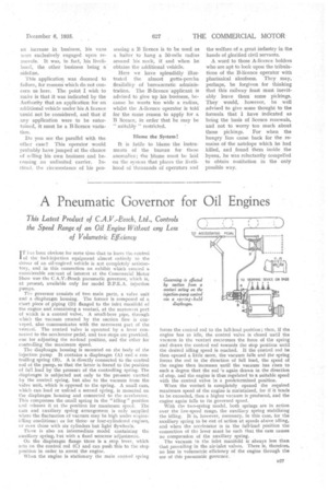
The governor consists of two main parts, a valve unit and a diaphragm housing. The former is composed of a short piece of piping (D) flanged to the inlet manifold of the engine and containing a venturi, at the narrowest part of which is a control valve. •A small-bore pipe, through which the vacuum created by the suction flow is conveyed, also communicates with the narrowest pai t of the venturi. The control Valve is operated by a lever connected to the accelerator pedal, and two stops are provided, one for adjusting the no-load position, and the other for controlling the maximum Speed.
The diaphragm housing is mounted on the body of the injection pump It contains a diaphragm (A) and a con-. trolling spring (B). A is directly connected to the control rod of the pump, so that the latter is forced to the position of full load by the pressure of the controlling spring. The diaphragm is subjected not only to the pressure exerted by the control spring, but also to the vacuum from the valve unit, which is opposed to the spring. A small cam, 1.; hich can load or unload a second spring, is mounted on the diaphragm housing and connected to the accelerator. This compresses the small spring in the " idling" position and releases it at the position for maximum speed. The cam and auxiliary spring arrangement is only 'supplied where the fluctuation of vacuum may be high under engineidling conditions; as for threeor four-cylindered engines, or even those with six cylinders but light flywheels.
There is also an intermediate model containing the auxiliary spring, hut with a fixed setscrew adjustment On the diaphragm flange there is a stop lever, which acts on the control rod (C) and can push this to the stop position in order to arrest the engine.
When the engine is stationary the main control spring
forces the control rod to the full-load position ; then, if the engine has to idle, the control valve is closed until the vacuum in the venturi overcomes the force of the spring and draws the control rod towards the stop position until the desired idling speed is reached. It the control rod be then opened a little more, the vacuum falls and .the sPring forces the rod in the direction of full load, the speed of the engine then increases until the vacuum has risen to such a degree that the rod -7s again drawn in the direction of stop, and the engine is thus regulated to a suitable speed with the control valve in a predetermined position.
When the venturi is completely opened the required maximum speed of the engine is maintained, for if it tends to be exceeded, then a higher vacuum is produced, and the engine again falls to its governed speed.
With the two-spring model, both springs are in action over the law-speed range, the auxiliary spring stabilizing the idling. It is, however,necessary, in this case, for the auxiliary spring to be out of action at speeds above idling, and when the accelerator is in the full-load position the connection of tin: lever must be such that the cam causes no compression of the auxiliary spring.
The vacuum in the inlet manifold is always less than that prevailing in the air-inlet valves. There is, therefore, no loss in volumetric efficiency of the engine through the use of this pneumatic governor.


