


A LORRY LOADING DEVICE.
Page 32
If you've noticed an error in this article please click here to report it so we can fix it.
A Résumé of Recently Published Patents.
We have from time to time reviewed in these columns various inventions which have had for their object the rapid and easy loading and unloading of motor vehicles. The majority of them have taken the form of devices in which the chassis is fitted with a plain platform, upon which are mounted rails, which receive the loose detachable load-carrying body, which is fitted with wheels suitably designed to run upon these rails. The equipment generally includes the necessary fittings whereby the removable body is securely fastened in place during such time as the vehicle is in motion. Generally these patents have been of British origin, and in most cases the idea has been that the removable body, when taken from We vehicle proper, should run on to a trailer, which can conveniently be moved about from place to place within the terminal warehouse or depot, wherein loading and unloading is to be effected. It may not be without interest to examine Specification No. 170,188,
which osiginates in. the 'U.S.A., the patentee being A. L. Rice, of New York. This deals with a 'similar device and illustrates American ideas on the same subject.
In this ease, instead of having movable trailers at the terminal points for the reception of the loose body, the latter is transferred to a platform. The more important features of this invention are concerned with the construction of the platform the means by which it can be regulated so as to accommodate itself to various • types of chassis, and the means by which alignment of the rails on the platform with those on the lorry proper may consseniently and easily be effected.
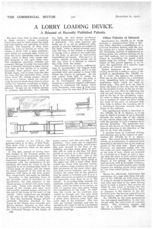
According to the particular form of the invention which is described in the specification, the side members of the chassis proper are fitted with plain angleiron rails. These rails extend the full length of the chassis, and upon them' run suitably grooved pulleys attached to the end of the frame of the body of the vehicle. Other angle-irons are attastbed to the sides of the frame of the body, so that the .horizontal flanges project outwards. Brackets attached to the frame of the chassis have inwardly projecting flanges, disposed so that when the body is in position they lie just over the horizontal flanges on the angles of 1:336 the body. By this means accidental vertical displacement of the loose body is prevented. The same brackets are made use of to act as additional safeguards to prevent sideways movement of the body, while a spring-actuated pawl near the rear of the chassis is designed to engage with a notch on the under side of the beady to prevent its inadvertent longitudinal movement. This pawl is, of course, capable of being moved out of the way when it is desired to remove the body from the frame. The platform is of course, sufficiently long to accommodate the longest body which is likely to be used, and it is also provided with raals similar to those with which the chassis is equipped. At the end remote from that, to which the vehicle is approached when the body is to be transhipped, the platform is hinged to a stationary support sufficiently strong to withstand the shocks which must inevitably come upon 4 from time to time, when the rear end of the chases
eess-s:es makes contact with the outer end of the platform. This outer end is supported by a couple of vertical bolts, which screw into nuts secured to the floor of the building, provision being made by suitable pits or wells in the floor for these screws to project in a downward direction below the floor level. One of the screws is of considerable length and projects above the platform, being fitted at the upper end with a hand wheel. Both screws are fittedwith sprocket wheels, and a suitable chain connects the two, so that. movement of the hand wheel operates both screws together, and by their rotation the outer end of the platform may be raised or lowered until it is at a height convenient to receive or discharge the removable body from or on to the chassis. A projecting ledge beneath the platform supports the underside of the chassis, when the latter is in contact, so that no sagging may take place during the transference of the body. In order that the tracks on the platform may readily be brought, into line with those on the chassis, the former are hinged at a point some distance away from the outer edge of the platform. The two rails are coupled together, and may be moved to the right or left in a horizontal plane by means: of a convenient lever and suitable. couplings.
Other Patents Of Interest:
Specification No, 170,079, by H. Wade (actually a communication from a German firm), describes a modification of a previous invention dealing with the cooling system for a motor vehicle in which the circulating medium is maintained at boiling point, the radiator serving not to cool that medium, but to condense and return to circulation the steam which results fropi the boiling. The principal object of this patent appears to be to cover the application of a suitable type of safety or control valve.
Rather ingenious is the additional cooling device for a radiator which is described in specification No. 170,07V, by H. L. Cole. He replaces the ordinary filler cap on the radiator by a miniature cowl, resembling both in shape and in application those which are used on board ship. The cowl is so set that it faces the front of the car, and the idea of the inventor is that, as the car travels, this cowl has the effect of collecting the cold air and forcing it into the radiator and to the top of the circulating water. In order to make the device more effective a number of raises are fitted inside the front of the cowl, so arranged that they help to deflect the incoming air in a downward direction towards the interior of the radiator.
The splashguard which is described in No. 170,081, by E. T. Barlow, is of the i 'type in which a current of air s directed towards the 'under side of the wheels 'of the vehicle where they are in contact with the ground-, in such a manner as to prevent splashing. The particular feature of this device to which the inVentor attracts attention is the direction of the jets of air from the nozzles.
A peculiar form of combined driving and steering axle is the subject of speci fication No. 170,119, by C. L. Heyermans. The actual driving mechanism involves, as is customary, a universal joint mounted in the direct line of the steering pivots of the stub axle. These pivots, however, are spherical ended, and the two ends are each supported in sockets at the ends of bars, which are mounted in a bracket on a frame in such a mariner that the pivot is held vertical under all conditions of movement under the influence of the springs. No continuous load-carrying axle is provided whatever, the two sets of parallel motion gear which support the steering pivots being carried by one long coiled spring or its equiva
• lenlItieans for effectively lubricating the mechanism of a rear axle form the subject of No. 170,173, by 0.1/ Cars, Ltd. A scoop or trough is mounted inside the rear axle case close to the main driving bevel in such a manner that surplus oil lifted by this wheel is flowing into the scoop, whence it is distributed by ducts or passages to the interior of the differential gear, the bearing supporting the bevel pinion, and to any other bearings. No. 170,174; by the same patentees as i
the last-named specification, s also concerned with the lubrication of rear-axle details. The inventors suggest the use of a hollow shaft, into which lubricant is infected.