


Patents Completed.
Page 28
If you've noticed an error in this article please click here to report it so we can fix it.
BALL BEARING.--C. W. Vosper.— No. 9,238, dated 19th April, 1906.—The ball bearing is constructed with provision for adjustment in the case of wear of the races. This is accomplished by providing a sleeve (B) carried upon the shaft (C) with ball races shaped as shown in the illustration. The sleeve (B) also has left and right-handed screw-threads at one end upon which a net (E) and lock-nut (F) are screwed. The nut (E) is provided with a coned part providing a race for an auxiliary set of balls. The outer races for the balls are formed in a sleeve (A), and the balls arc admitted to the bearing through holes closed by screwed plugs.
RESILIENT WHEEL.—W. T. G. Ellis. -No. 5,681, dated 9th March, 1906.—This invention is for the purpose of protecting the tires of heavy motor vehicles and les sening their liability to "skid." The metal rim (I) is secured to the ordinary wooden felloe (2), and curved metal plates (3) are secured on each side of the felloes by the bolts 14). Over the metal rim a rubber tire (6) is secured between the plates (3) and this is built up of two layers of rubber, the inner one being softer and more resilient than the outer. Over the tire are placed protecting plates (7) having roughened surfaces and slotted lugs (8). The bolts (4) pass through the slots and enable the plates (7) to move with the compression of the tire.
LUBRICATOR.—W. F. C. Ward.— No. ,839, dated 7th November, 1905.— This lubricator comprises a plug (a) adapted to be either continuously or in termittently rotated in a barrel (5) communicating with a reservoir or conduit (ell for the lubricant. The plug is pro vided with helical grooves (c), which automatically withdraw the lubricant from the reservoir or conduit through orifices (€). By the rotation of the plug the lubricant is caused to traverse the threads or grooves (c) and escape by the outlets (1) to the various parts to be lubricated.
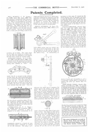
SHOCK ABSORBER.—H. Sans.—No. 15,322, dated 5th July, 1906.—When a ve hicle wheel passes over an uneven surface, it is forced downwards, in the case of a depression iii the road, by the sum of the spring pressure and the weight of the vehicle body. In surmounting an elevation the wheel has to compress the spring against the inertia of the vehicle body. The resulting oscillations due to the spring and body attempting to assume their normal relative positions are therefore of greater amplitude after the wheel has entered a depression than when it has surmounted an elevation. The result is that a shock-deadening device must act more powerfully when the wheel tends to
enter a depression than when it has a tendency to rise. The object of this invention is to meet these requirements by attaching the ends of a leaf spring to arms (7), which have cylindrical extensions (8i at their opposite ends. These extensions (8) are embraced by art eccentrically-shaped portion (11) within which is a friction band (151 of leather. The portions (11) are made in one with arms (6) pivoted to the vehicle framing. The portions (11) are made to grip the parts (8) by springs (17 and l8, so that any upward
movement of the arms (7) caused by the wheel passing over an elevation will tend. to open the portions (11) and reduce friction between them and the parts (8), but any downward movement will cause the portions (11) to grip the parts (8) and prevent rapid return of the body to its normal position.
CONTACT BREAKER.—Electric
Ignition Co., Ltd.—No. 4,057, dated 19th February, 1906.—The object of this invention is to provide a wipe contact of the type in which co-operating tappet members (c, gl) are employed. For multi. cylinder engines a series of co-operating arms (c, gl) are provided, all of the arms (Cl being reciprocated by a single cam (e)_ The contact members (gl) are spring-controlled, but are limited in their movement by stops, so that these arms do not follow the arms (r) throughout the whole movement of the latter, whereby the requisite break is obtained. It will be seen that in addition to the mere break effected by the contact and separation of the cle ments of each pair of members (c, gl) a considerable wiping effect is obtained by making the arms (gl) shorter than the arms (c).
TWIN SOLID TYRES.—Struck.—No, 16,241, dated 18th July, 1906.--To provide a striking surface each tyre has bedded in it a plate (d.), one edge (e) of which is 'flush with the exterior of the tyre, and beats upon the rim (a). When first placing the tyres in position they may be driven on the rim from opposite sides, as shown in the drawing, and secured in place by wires (5,c) mounted in grooves in the rim. To remove, say, the right-hand tyre, all that is necessary is to cut the wires (5 and el and drive the left-hand tyre to the right, whereupon it will force off the rim. A new tyre can now be mounted on the left side of the rim, and the striking faces (e) of both tyres will then be on the same side.