


CONFOUNDING THE " EXPERT "
Page 40
Page 41
If you've noticed an error in this article please click here to report it so we can fix it.
By J. Pickles, A.M.I.Mech.E.
THE reactions ot most people entering the motor industry and the road transport world may be traced fairly simply. There is, first, an impression of the vast amount of knowledge which must be assimilated to ensure even a reasonable competence. This feeling of awe continues for a long period. One day the novice realizes that he has, in an incredibly short period, acquired more knowledge than he had thought possible. He is then qualified to throw out his chest and proclaim that he knows all about his subject, and is, in fact, an expert.
Whether he passes to the third and last stage depends on the individual. He may, in many cases, continue through life in a prolongation of stage two, knowing "more ways of how a thing cannot be done than anyone else." Should the individual graduate to the last phase, he will be appalled at the vast field of knowledge which his grasp of a little of it has revealed, and he will pass his life without uttering the phrase "I know," but rather, in all humility, will begin his theories with "1 believe."
It is in this last phase that, as a useful member of the community, he may, while finding new things, discover that many tenets, accepted as true because they came from the lips of experts, have no foundation in fact when exposed in the light of logic. .
Independent Suspension
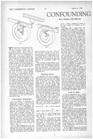
As an instance, a proposed new chassis was to have, at the front, an independent suspension system of the Porsche type. The construction was based on a heavy cross-member terviinating in a bracket containing bearings, for the articulation of two levers mounted one above the other. These levers were extended rearwards and were hinged to a carrier on which was mounted the road wheel. This linkage appeared eminently satisfactory, and although the levers were of cantilever type, in which one end was fixed and the load was applied at the other, there were, after all, two of them to carry the weight. (Fig. 1.) It was then suggested that the rear wheels should be similarly carried, but although two levers were necessary to maintain the required king-pin angle in the case of the front end, no such limi ati tation occurred at the rear. (Fig. 2.) But the expert said that if two levers were necessary at the front and were of robust proportions, a single lever at the rear would require to be of the combined strength of the front two and, therefore of formidable weight and bulk.
This reasoning would appear to be common sense. Calculations were made, however, and the seemingly practical view was disproved. It was just one more case of what looks right being right only if the viewer knows what he is looking for.
Sideways Force
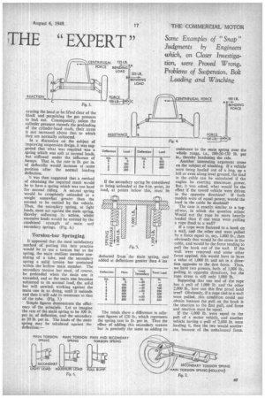
To illustrate the case in point, a hypothetical chassis will be considered with proportions such that the rolling radius of the wheel is 14 ins., and the levers pivoted on the wheel carrier equidistant on each side of the wheel centre, with an 8-in. spread. The greatest force to be resisted by the levers is the sideways force at the tyre, where it meets the road, caused by cornering. In the case of the lower lever the force is in the same direction as that on the Lyre, and, as the wheel endeavours to twist around this point by turning under, the upper lever is loaded in a direction opposite to the lower one.
Supposing that the side force be 100 lb., the bending load on the end of each lever may easily be calculated. The lower lever will be subjected to a
18 force of — x 100 = 225 lb., and the 8 10 upper a force equal to — x 100 = 8 125 lb. (Fig. 3.) With a single lever, only 100 lb. is applied at the lever end. (Fig. 4.) This curious result may be better appreciated by simplifying the argument. With the double-lever suspension the points at which the forces are applied may be considered as being acted upon by a crowbar substituted for the wheel. In this case it will readily be seen that the upper may serve as a fulcrum, and the load at the crowbar end is multiplied at the lower point, whilst a similar condition is found if the lower point be imagined as the fulcrum.
Although with a single lever the bending force is only 100 lb., there is, in addition, a torsional force tending to .
twist it, but this is small compared with the other forces. In the example which instigated the discussion, it was found by accurate analysis that, taking, as a basis, the stronger of the levers in the twin-arm type, the use of a single arm required it to be proportioned so that it was 25 per cent. weaker. In other words, after taking one lever away, the remaining one could be made lighter.
In another instance, the problem of the load on cylinder-head studs was under discussion, and one member of the group said that a lengthy argument had been held in correspondence in The Aeroplane" to the effect that the load on these studs was determined by the tightening-down force, and further loading, caused by gas pressure, did not increase the tension. Once again the voice of the expert joined in to point out that obviously if a part were stressed, the addition of another force could only increase the stress.
In examining the precise nature of this problem it assists, as always, to simplify things by reducing the example to its minimum number of components. In this case I will take a cylinder in which is a piston. The cylinder end is closed by a flat plate held in position by two studs. The act of tightening down the cylinder-head nuts tends to pull the studs out of their tapped holes and their resistance to this is a measure of the stress imposed by the preloading.
Each of the two studs will be considered to be stressed with a load of 1,000 lb.: in other words, the cylinder head is being pulled into contact with the block by two forces of 1,000 lb. each.
Load on Bolts
It will be appreciated that a stud or bolt behaves exactly as a spring, in that if a force be applied to it it will deflect, and if the elastic limit is not exceeded, will return to its original dimensions on removal of the load. It is, however, easier to imagine a spring of helical form, and so the holding-down force on the head will be considered as. two springs. (Fig. 5.) To increase the load in these springs their compression must be increased, as obviously, one cannot increase a spring's compression without increased pressure. With this in mind let us consider that a gas pressure of 1,000 lb. occurs in the cylinder. This is insufficient to overcome the combined pull of the two springs, so that the cylinder head remains in contact with the block, and as the springs are, in consequence, not further compressed, they do not carry an increased load.
If the cylinder pressure be increased so that it slightly exceeds the stud loading, the springs will be compressed,
causing the head to be lifted clear of the block and permitting the gas pressure to leak out. Consequently, unless the cylinder pressure exceeds the preloading of the cylinder-head studs, their stress is not increased above that to which they are normally subjected.
In a discussion on the subject of improving suspension design, it was suggested that what was required was a spring which was soft at normal loads, but stiffened under the influence of bumps. That is, the rate in lb. per in. of deflectitin would increase at some position after the normal loading deflection.
/t was then suggested that a method of obtaining the required result would be to have a spring which was too hard for normal riding. A second spring would be completely unloaded at a weight somewhat greater than the normal to be carried by the vehicle. Thus, the secondary spring, at light loads, must act against the main spring, thereby softening its action, whilst excessive loads would be resisted by the combined strength of main and secondary springs. (Fig. 6.)
Torsion-bar Springing
It appeared that the most satisfactory method of putting this into practice would be to use a torsion bar as the spring, the main resilient member consisting of a tube, and the secondary spring a solid torsion bar contained within the hollow main member. The secondary torsion bar must, of course, be preloaded when the main one is extended, and as the main one becomes subjected to its normal load, the solid bar will unwind, working against the main one in so doing, until it unloads and then it will add its resistance to that of the tube. (Fig. 7.) Simple figures demonstrate the efficiency of the principle. Let us imagine the rate of the main spring to be 100 lb. per in. of deflection, and the secondary as 20 lb. per in. The loads of the main spring may be tabulated against the deflection:— If the secondary spring be considered as being unloaded at the 4-in, point, its load, at points below this, must be deducted from the main spring, and added at deflections greater than 4 ins The totals show a difference in adjacent figures of 120 lb.. which represents the spring rate in lb. per in. Thus the effect of adding this secondary torsion bar is precisely the same as adding its assistance to the main spring over the whole range, i.e., 100-20-120 lb. per in., thereby hardening the ride.
Another interesting argument arose on the subject of winching. If a vehicle were being hauled out of a bog, up a hill or even along level ground, the load in the cable can be calculated if the engine be exerting maximum power. But, it was asked, what would be the effect if the towed vehicle were driven in the opposite direction? If both models were of equal power, would the load in the cable be doubled?
The case is exactly similar to a tugof-war, in which the question arises: Would not the rope be more heavily loaded than if one team were culling a rope fixed to a wall?
If a rope were fastened to a hook on a wall, and the other end were pulled by a force equal to, say, 1,000 lb., then obviously that would be the stress in the cable, and would be the force tending to pull the hook out of the wall. If the wall were removed and some other force applied, this would have to have a value of 1,000 lb. and act in a direction opposite to the first force. Thus, we have two powers, both of 1,000 lb., pulling in opposite directions, but the rope stress is still only 1,000 lb.
Supposing that one end of the rope has a pull of 1,000 lb. and the other 2,000 lb.. how can this first proof hold true? Obviously, if a rope tied to a wall were pulled, this condition could not obtain because the pull on the hook is the reaction to the first pull, and force and reaction must be equal.
If the 1.000 lb. were equal to the pull of a motor vehicle, and another vehicle having a pull of .2,000 lb. were hauling it, then the two would accelerate, because of the unbalanced force.