


WHY HAS THE HYPOID GEAR BEEN NEGLECTED?
Page 36
Page 37
Page 38
If you've noticed an error in this article please click here to report it so we can fix it.
Despite its Silence and Strength the Hypoid Gear Finds Little Favour in this Country. Our Contributor Discusses the Technical Aspects of Other Gears in Comparison
By A. W. Haigh,
A.M.I.Mech.E.
THE two kinds of final-reduction gear in common use on commercial vehicles are the spiral-bevel combination for the lighter types of both goods and passenger machine, and the worm drive for the heavies in the two classes Both types give excellent service, but, nevertheless, each suffers from disadvantages which engineers have been attempting to eradicate since the units were first invented..
The spiral-bevel gear is a direct descendant of the straight
bevel unit, the process of evolution being a simple curving of the teeth as originally carried out by the Gleason concern of America. The necessity of such a development becomes fairly obvious when the action of a pair of straight-bevel gears—
the original form of final reduction gear on motor vehicles—is analysed.
In theory, when two such gears are rolled together, the whole length of a tooth on the pinion immediately contacts the whole length of the mating gear. When this occurs, the entire load is passed on with considerable shock, and for this reason heavily loaded straight-bevel gears, with few teeth in the pinion, as is common in rear-axle drives, are prone to early failure because of the resultant distortion and high unit pressure.
The condition is further aggravated by slight inaccuracies in cutting or .mounting the gears, which cause end-loading of the teeth, or, in other words, contact, instead of follow /1 ing theory; is effected at each end of the teeth and Fig. 2. not along the full length. Consequently, distortion and noisy operation are increased, and fatigue life decreased.
End-loading can, however, be relieved by cutting the teeth with their extremities thinner than their centres, thus ensuring localized loading in the middle of the teeth where it can cause least damage. But this improvement neither eliminates shock, nor quietens the gears, to any appreciable extent. 1 he development of the spiral-bevel unit was the proper answer.
A spiral-bevel gear can be con sidered as an infinite number of extremely thin straight-bevel gears, each one of which is staggered slightly from its two adjacent laminations. Thus, although the action of each of these thin gears is that of a straight-bevel unit, in that the torque transmission is accompanied by shock, the period of time between the innumerable shocks on a tooth is so small that the action becomes continuous.
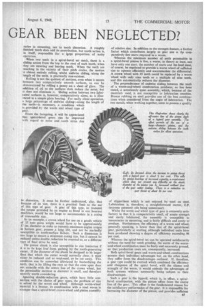
Further analysis of the gears, when considered as a number
of thin plates, shows that at no time is the entire load transmitted by one tooth alone, as is the case with straightbevel gears. Figs. 1, 2 and 3 show teeth of a straight-bevel pinion in mesh with a large gear. In Fig. 1, tooth A is just entering into mesh; Fig. 2 shows the position of tooth A when a second tooth, B, on the pinion, is at the point of first contacting a tooth in the gear, and Fig. 3 gives the position of teeth A and B when a third tooth is just entering into mesh. It will be noted that neither tooth A nor tooth C is actually in mesh, and therefore tooth B alone is taking the load.
Now imagine that tooth A has been so twisted along the root cone of .the pinion that the other end to that shown in Fig. 3 is in the position B, and that tooth B has been similarly twisted until its other end is in position C. It will be immediately agreed that, under these conditions, more than one tooth is in mesh even at the most disadvantageous relative position of the gears as shown.
In practice, the teeth of a spiral-bevel pinion are formed so that their opposite ends, as previously referred to, are positioned still farther back than the positions indicated by B and C, so that considerable overlapping of their two ends, an increase in the number of teeth in mesh, and a continuous contact line are all achieved.
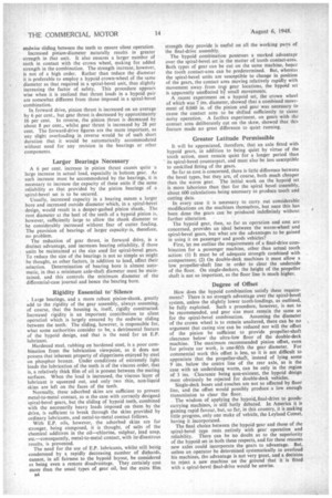
When the teeth are cut, the radius of curvature of those
in the pinion is made somewhat smalla than that of the gear teeth. As a result, contact is made over a restricted area only, as shown in Fig. 4. The actual location of this contact area can be controlled by varying the machine settings, which, in effect, move the centres of curvature of the teeth relative to each other. In this way, tooth loading can be controlled.
For instance, if the torque to be transmitted be con tinuously high, the contact area would be arranged to occur towards the toe, or small end of the tooth when the gears were unloaded, for, as more load is applied, the area tends to move along the tooth towards the heel. If, then, in the case of no load, the contact area were at the normal position, that is, in the centre of the tooth, the addition of high torque might cause it to move right to the back, and so bring about the undesirable condition of end-loading of the teeth.
The movement of the tooth contact-area is not alone governed by load under operating conditions, as many other factors also affect it. A relatively flexible mounting for the gears, such as would be provided by an inadequate axle casing, would cause misplace / ment of the area, as would incorrect location of the crown wheel or pinion.
In the, latter event, in addition to causing the repositioning of the con
Fig. 3. tact area, backlash between the gears
is also affected in the approximate ratio of 0.001 in. increased backlash for every 0.001 in. movement of either gear or pinion away from its correct cone centre. There is the same amount of decrease for relative movement towards the cone centres.
Deviations of this nature from the ideal cause unwanted tooth distortion under load, which increases tooth stresses, and encourages noisy operation. If the backlash becomes too great the gears tend to clatter, and if at a lower figure than the recommended minimum, they tend to whine. An incorrectly positioned contact area, whether it be too far towards one end of the tooth or arranged
obliquely, can
cause a characterGEAR TOOTH istic moan or growl similar to that encountered with badly worn parts.
Noise troubles are not, unfortunately, entirely
due to inaccuFig. 4, ( PINION TC>C5TH RA01115 ...--- RADIUS
racies in mounting, nor to tooth distortion. A roughly finished tooth does add its contribution, but tooth action is, in itself, responsible for a large proportion of noisy operation.
When two teeth in a spiral-bevel set mesh, there is a sliding action from the top to the root of each tooth, when they are entering and leaving mesh. When the teeth are touching in the vicinity of their pitch circles, the motion is almost entirely rolling, whilst endwise sliding, along the length of the teeth, is practically non-existent.
Rolling is not the quietest of motions, even when it occurs between two comparatively smooth surfaces, as can be demonstrated by rolling a penny on a sheet of glass. The addition of oil to the surfaces does reduce the noise, but it does not eliminate it. Sliding action between two lubricated surfaces is, however, comparatively silent, as is illustrated in a simple plain bearing. For really silent operation. a large percentage of endwise sliding—along the length of the teeth—is necessary, a condition which is provided by the worm and wheel type of gear.
From the foregoing, it will be appreciated that spiral-bevel gears can be improved with regard to noise and tooth stress due to distortion. It must be further understood, also, that because of its size, there is a practical limit to the use of this type of gear. A gear of this type, to transmit the torque provided by an engine as fitted in our heaviest machines. would be too large to accommodate in a casing of reasonable size.
As an example, a crown wheel for use on a goods vehicle of 15 tons gross weight would have to be approximately 17 ins, diameter in order to transmit maximum engine torque in bottom gear, possess ,a long life, and not be markedly susceptible to tooth-surface failure. Such a dimension is too large to ensure a minimum casing size, but it cannot be reduced unless double reduction be resorted to, or a different type of final drive be used.
The pinion shank is also susceptible to size limitation if it is to be kept free from gashing by the tooth-generating cutter_ If the diameter of the shank be designed to be larger than that which the cutter would normally clear, it must either be reduced and so weakened, or be cut away. This condition can be somewhat alleviated by bastardizing the teeth, that is by lifting the root so that the cone apex does not coincide with the centre line of the crown wheel, but the permissible increase in diameter is small, and therefore scarcely worth considering.
Ignoring double-reduction gears, which have little connection with the choice of gear types, the problem of size is solved by the worm and wheel. Although worm-wheel material is a bronze, its combination with a steel worm is stronger than a spiral-bevel crown-wheel and pinion assembly
of relative size. In addition to the strength feature, a further factor which contributes largely to gear size is the comparatively few starts required in a worm.
Whereas the minimum number of teeth permissible in a spiral-bevel pinion is five, a worm, in theory at least, can have only one start; the number of starts and the lead must, of course, be regulated to provide a worm wheel of sufficient size to operate efficiently and accommodate the differential. A crowti wheel with 45 teeth could be replaced by a worm wheel with only nine teeth or a multiple of nine teeth, and this automatically reduces the diameter.
The preponderance of endwise sliding between the teeth of a worm-and-wheel combination produces, as has been stated, a notoriously quiet assembly, which, because of the materials used, is not susceptible to lubrication troubles. Bronze rubbing on steel provides one of the best combinations when considered from the angle of lubrication. The two metals, when working together, seem to possess a quality of slipperiness which is not enjoyed by steel on steel. Lubrication is, therefore. a straightforward matter, E.P. (extreme pressure) oils being unnecessary. Whilst the worm and wheel type of gear is eminently satisfactory in that it is comparatively small, of ample strength and easily lubricated, the assembly is susceptible to inaccuracies in mounting, and is fairly difficult and costly to produce. Furthermore, the efficiency of a worm and wheel, generally speaking, is lower than that of the spiral-bevel gear, particularly at starting, although individual units have been produced showing a degree of efficiency exceeding 98 per cent. Whereas the spiral-bevel set can be operated satisfactorily without the need for tooth grinding, the worm of the wormand-wheel combination must be finely and accurately ground, so that production costs are, consequently, increased.
Both spiral-bevel gears and worm-and-wheel combinations possess their individual advantages but, on the other hand, they suffer from the disadvantages outlined. If, therefore, a gear type could be evolved which combined the efficiency and cheapness of the spiral bevel, with the silence and strength of the worm, it would embody the advantages of both systems without necessarily being • subject to their disadvantages.
Such a gear is the hypoid, which is, in effect, a spiralbevel combination, with the pinion offset from the centre line of the gear. This offset is the fundamental reason for the satisfactory performance of the gear. It is responsible for increasing the diameter of the pinion, and provides sufficient endwise sliding between the teeth to ensure silent operation.
Increased pinion-diameter naturally results in greater strength in that unit. It also ensures a larger number of teeth in contact with the crown wheel, making for added strength in the combination. The strength increase, however, is not of a high order. Rather than reduce the diameter it is preferable to employ a hypoid crown-wheel of the same diameter as that required in a spiral-bevel unit, thus slightly increasing the factor of safety. This procedure appears wise when it is realized that thrust loads in a hypoid pair are somewhat different from those imposed in a spiral-bevel combination.
In forward drive, pinion thrust is increased on an average by 6 per cent., but gear thrust is decreased by approximately 16 per cent. In reverse, the pinion thrust is decreased by about 8 per cent., whilst gear thrust is increased by 28 per cent. The forward-drive figures are the more important, as any slight overloading in reverse would be of such short duration that it would be automatically accommodated without need for any revision in the bearings or other components.
Larger Bearings Necessary'
A 6 per cent, increase in pinion thrust causes quite a large increase in actual load, especially in licittom gear. As such increase must be accommodated by the bearings, it is necessary to increase the capacity of these units if the same reliability as that provided by the pinion bearings of a spiral-bevel set is to be secured.
Usually, increased capacity in a bearing means a larger bore and increased outside diameter which, in a spiral-bevel design, would result in a deeper-gashed pinion shank. The root diameter at the heel of the teeth of a hypoid pinion is, however, sufficiently large to allow the shank diameter to be considerably increased without fear of cutter fouling. The provision of bearings of larger capacity, is, therefore. no problem.
The reduction of gear thrust, in forward drive, is a distinct advantage, and increases bearing reliability, if those units be maintained at the size used for spiral-bevel gears. To reduce the size of the bearings is not so simple as might be thought, as other factors, in addition to load, affect their selection. Determination of bearing bore is almost automatic, in that a minimum axle-shaft diameter must be maintained, and this controls the minimum diameter of the differential-case journal and hence the bearing bore.
Rigidity Essential to Silence
, Large bearings, and a more robust pinion-shank, greatly add to the rigidity of the gear assembly, always assuming. of course, that the housing is, itself, rigidly constructed. Increased rigidity is an important contribution to silent operatimi which is largely ensured by the endwise sliding between the teeth. The sliding, however, is responsible for, what some authorities consider to be, a detrimental feature of the hypoid design, and that is the need for an E.P. lubricant.
Hardened steel, rubbing on hardened steel, is a poor combination from the lubrication viewpoint, as it does not possess that inherent property of slipperiness enjoyed by steel on phosphor bronze. Under conditions of extremely light loads the lubrication of the teeth is of the viscous order, that is, a relatively thick film of oil is present between the mating surfaces. When the load is increased, the viscous layer of lubricant is squeezed out, and only two thin, non-liquid skins are left on the faces of the teeth.
Normally, these adsorbed skins are sufficient to prevent metal-to-metal contact, as is the case with correctly designed spiral-bevel gears, but the sliding of hypoid teeth, combined with the necessarily heavy loads imposed on them by the drive, is sufficient to break through the skins provided by ordinary lubricants, and metal-to-metal contact follows.
With E.P. oils, however, the adsorbed skins are far stronger, being composed, it is thought, of salts of the chemical additives in the oil—chlorine, sulphur, lead soap, etc.—consequently, metal-to-metal contact, with its‘disastrous results, is prevented.
The need for the use of E.P. lubricants, whilst still being condemned by a rapidly decreasing number of diehards, cannot, in all fairness to the hypoid layout, be considered as being even a remote disadvantage. They certainly cost more than the usual types of gear oil, but the extra film 54 strength they provide is useful on all the working parts of the final-drive assembly.
The hypoid combination possesses a marked advantage over the spiral-bevel set in the matter of tooth contact-area. Both types of gear can be cut on the same machine, hence the tooth contact-area can be predetermined. But, whereas the spiral-bevel units are susceptible to change in position of the gears, the contact area moving relatively rapidly with movement away. from true gear locations, the hypoid set is apparently unaffected 14 small movements.
A recent experiment on a hypoid set, the crown wheel of which was 7 ins, diameter, showed that a combined movement of 0.040 in. of the pinion and gear was necessary to cause the contact area to be shifted sufficiently to cause noisy operation. A furthes experiment, on gears with the contact area deliberately cut on the skew, showed that this feature made no great difference to quiet running.
Greater Latitude Permissible
It will be appreciated, therefore, that an axle fitted with hypoid gears, in addition to being quiet by virtue of the tooth action, must remain quiet for a longer period than its spiral-bevel counterpart, and must also be less susceptible to unskilled fitting of the gears.
So far as cost is concerned, there is littli difference between the bevel types, but they are, of course, both much cheaper than the worm gear. The initial work on the hypoid set is more laborious than that for the spiral bevel assembly, about 600 calculations being necessary to produce tooth and cutting data. In every case it is necessary to carry out considerable modifications on the machines themselves, but once this has been done the gears can be produced indefinitely without further alteration.
The hypoid gear, then, so far as operation and cost are concerned, provides an ideal between the worm-wheel and spiral-bevel gears, but what are the advantages to be gained in using it on passenger and goods vehicles? •
First, let me outline the requirements of a final-drive combination for a passenger machine, other than actual tooth action: (1) It must be of adequate strength combined with compactness; (2) On double-deck machines it must allow a low propeller-shaft line in order to clear the underside of the floor. On single-deckers, the height of the propeller shaft is not so important, as the floor line is much higher.
Degree of Offset
How does the hypoid combination satisfy these requirements? There is no strength advantage over the spiral-bevel system, unless the slightly lower tooth-loadings, as outlined, be fully exploited. Such a procedure, however, is not to be recommended, and gear size must remain the same as for the spiral-bevel combination. Assuming the diameter of the crown wheel is to remain unaltered, there can be no argument that casing size can be reduced nor will the offset of the pinion be sufficient to provide propeller-shaft clearance below' the ultra-low floor of the double-deck machine. The maximum recommended pinion offset, even for private car work, is one-fifth the gear diameter. For commercial work this offset is less, so it is not difficult to appreciate that the propeller-shaft, instead of lying some 9 ins, below the centre line of the rear axle, as is the case with an underslung worm, can be only in the region of 3 ins. Clearance being non-existent, the hypoid design must obviously be rejected for double-deck vehicles. Single-deck buses and coaches are not so affected by floor line, and the offset would possibly produce a low enough transmission to clear the floor.
The wisdom of applying the hypoid. final-drive to goodscarrying machines, is still hotly debated. In America it is gaining rapid favour, but, so far, in this country, it is making little progress, only one make of vehicle, the Leyland Comet. having it incorporated. The final choice between the hypoid -gear and those of the spiral-bevel type rests entirely with gear operation and reliability. There can be no doubt as to the superiority of the hypoid set in both these respects, and for these reasons new axles could incorporate the gears to advantage. But. unless an operator be determined systematically. to overload his machines, the advantage is not very great, and a decision to reject a new machine on the ground that it is fitted with a spiral-bevel final-drive would be unwise.