


A Co-axial Engine Starter
Page 36
If you've noticed an error in this article please click here to report it so we can fix it.
A Résumé of Patent Specifications that Have Recently Been Published
_n _n
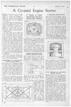
FROM the Ford Motor Co., Ltd., 88, Regent Street, London, W.1, comes, in patent No. 553,893, a design for a starter-motor coupling mechanism suitable for an• engine in which the starter. and the crankshaft are co-axial.
In the drawing, the starter-motor is shown with a pinion (2) which meshes with three planetary gears (1). The latter are attached to a second set of pinions (4) which mesh with a stationary internal gear ring (5). When the motor runs, the spider carrying the planets is thus driven at a reduced speed.
On three stubs on the spider are three rocking shoes (3), which travel in a wide. channel turned in the flywheel. Normally, they are just clear of the channel, but when the motor is energized small friction clutches associated with the pinions (4) turn the shoes and bring them into contact with the inside rim of the channel. A powerful self-wedging action is thus set up which couples the spider to the flywheel, and so rotates the engine. The spider itself is a Close fit around a central boss on the flywheel, anti the wedging _action forces this also into contact, and further solidifies the drive. So soon as the engine overruns, the shoes are automatically .throwp out of engagement, and the starter drive disconnected.
Apart from the subject matter of the patent, the specification also discloses some interesting detailsof the latest trend of Ford engine design.
IMPROVEMENT TO NOVELS ELF. LAYING TRACK •GEAR
IN our issue dated September 4, 1942, AT described a track layingvehicle in which a single iiheer on -each side was fitted with a, jointed. polygon of rigid track members, at least one of which was always lying in contact with the ground. Patent No. 553,905, from 0. Singer and C. Dew, 157, Green Dragon Lane, London, N.21, shows an addition to the system intended to overcome a slight defect of the earlier
type. , , •
It has been found that, in certain circumstances, there is,a tendency for the track members to sag away from the bottoin' of the wheel, especially in the momentary position illustrated, which two of the treads are in ground contact. A sag at the bottom would, by the geometry of the system, cause a lift on the top side and it has been found to be possible for -the wheel to become disengaged.
To avoid this, it is proposed to fit a pair of triangulated chains (4) which fOrm complete loops around rollers (1,, 2 and 3). By this means, the upper and lower tracks are effectively prevented from parting and thus the escape of the wheel teeth is prevented.
TORSION SPRINGING FOR' CONTACT-BREAKER POINTS.
I T is essential that the return spring of a contact breaker should have a high, natural frequency of vibration, if bounce is to be minimized, -In this connection a torsion-rod spring is
shown in patent No. 553,538, by Joseph Lucas, Ltd., and E. Watson, both of Great king Street. Birrningham, 19.
In the drawing, 4 is the stationary contact and 3 the blade carrying the moving point. The blade is bent to a U-shape to grip block 5 which' rubs on the cam. The blade is brazed oil to a tube (1), which, mounted in bearings, forms the rocking pivot. To one end of the tube is secured a squareended wire (2) which acts as the torsion spring, the other end being held in the rotatable-clip 6.
A TWO-PIECE ALLOY PISTON
ALIGHT-ALLOY piston, with a cast-in steel connector, is shown in patent No. 553,810, by the Permold
, Co., Medina, Ohio, U.S.A.' One of the objects of the design is to prevent much of the' heat of the piston crown from rea,ching the skirt, thereby reducing expansion troubles of the latter.
The crown and the skirt are entirely separate units, connected by on.y a steel U-section arch ' (2); this is attached to the crown by a cast interlock (1) and to the skirt by a cast-in joint located around the gudgeon-pin boss. At the latter point the arch is expanded into a pair of rings (3), which embrace the gudgeon-pin bore.
The differential expansion between the steel and the light alloy can, therefore, set up no stresses, because the
skirt can approach or recede from the head as may be necessary. Although the interlock (1) is the only actual ..fixing, the close fit between the arch and the head provides sufficient area to transmit the power forces. Another advantage of the design is that the piston can be cast in a metal mould without the need for sand cores. '
NOVEL METHOD OF ATTACHING BRAKE FACINGS
THE use of rivets for securing brake". shoe facings has many disadvantages, and patent No. 553,741 shows an ingenious method of attachment without the use of any foreign material in the friction surface. The patentee is Bendix Aviation Corpdration, South Bend, Indiana., U.S.A.
The facing is provided with tapped holes for the reception of screws which pass through holes in the webs of the brake shoes. The facings, and the screws, are both madg from similar material, that is, a mixture of synthetic resin and asbestos. When the screws are inserted a Solution of thermo-setting plastic is used to wet
both the screws and the holes. The heat generated under operating conditions solidifies the plastic and converts the screws and the facing into a onepiece structure. The facing can thus be permitted to wear right down to the shoes without the risk of scoring the drums.