


A Dual-control Injection Pump
Page 48
If you've noticed an error in this article please click here to report it so we can fix it.
A Resume of Patent Specifications that Have Recently Been Published
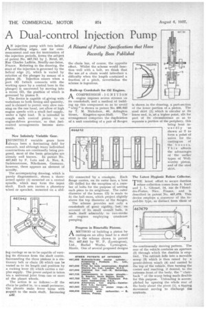
A N injection pump with two helical 1-1-controlling edges, one for cornmencement.and one for termination of the injection periods, forms the subject of patent No. 467,741 by J. Retel, 67, Rue Charles Laffitte, Neuilly-sur-Seine, France. Referring to the drawing, the start of the injection is governed by the helical edge (1), which is varied by rotation of the plunger by means of a pinion (3). Injection ceases when a port (4) (which connects with the working space by a central bore in the plunger) is uncovered by moving into a recess (2), the position of which is governed by pinion 5.
The device is capable of giving wide variations to both timing and quantity, and is claimed to permit very slow running on the one hand, yet allow of high engine speeds with a small fuel supply, under a light load. It is intended to couple each control pinion to an engine-driven governor, so that fuelcontrol arrangements become automatic.
New Infinitely Variable Gear.
I NFINITELY variable gears have always been a fascinating field for research, and although many individual constructions are continually being proposed, most dl the basic principles are already well known. In patent No. 467,942 by F. Lots and A. Nau, 8, Sudetenstrasse, Nikolas-see, Germany. however, there appears an element of novelty.
The accompanying drawing, which is purely diagrammatic, shows a threearmed spider (1) mounted on a central spindle, which may form the input shaft. Each arm carries a planetary wheel or sprocket, mounted on a slid ing carriage so as to be capable of vary ing its distance from the shaft centre. Surrounding the three pinions is a stationary belt or chain (3) which can be varied as to its length and position by a rocking lever (2) which carries a surplus supply. The power output is taken via a universal joint from one or more of the planet wheels, The action is as follows:—If the chain be pulled in, to a small perimeter, the planets make fewer turns with respect to the main shaft. Increasing B42 the chain has, of course, the opposite effect_ Whilst the scheme would functionwell with a belt, we think that the use of a chain would introduce a difficulty when the length contained a fraction of a pitch, nevertheless the scheme is ingenious.
Built-up Crankshaft for Oil Engines.
A COMPRESSION-IGNITION PA. engine imposes severe stresses on its crankshaft, and a method of building up this component so as to avoid " whip" is shown in patent No. 466,442 by T. M. Nicholson, 40, Arlington Street, Kingston-upon-Hull; The arrangement comprises the duplication of a unit consisting of a pair of flanges
(I) connected by a crankpin. Each flange carries, on its outer face, a boss (2) drilled for the reception of a number of bolts for the purpose of uniting each piece to its neighbour. The outer diameter of the bosses (2) is made to fit the ball races, which project slightly above the top diameter of the flanges.
The scheme provides not only a crankshaft of great rigidity, but, on account of its small overall bulk, it lends itself admirably to two-stroke oil engines employing crankcase pumping.
Progress in Bimetallic Pistons.
A METHOD of building a piston by
casting-on an alloy head to a steel' skirt is the scheme shown in patent No. 467,845 by W. P. (Lymington), Ltd., Radial Works, Lymington, Hants. One of several proposed designs
-s shown in the drawing, a part-section of the lower portion of a piston. The steel skirt (I) which is circular at its lower end, is, at a higher point, slit for part of its circumference so as to separate a portion of the periphery, this
being bent inwardly as shown, at 2 to form a point of union for the casting-on of the bosses. This affords the advantages of the earlier types of Wellworthy piston, and of the steel skirt, The Latest Hygienic Refuse Collector,
tHE latest effort to secure dustless I refuse collection comes from A. Tcart and J. L. Gitenet, 14, rue de l'Hoteldes-Postes, Nice, France, and is described in patent No, 467,479. This device employs a conveyor of the toand-fro type, as distinct from those of
the continuously moving pattern. The rear of the vehicle contains an aperture (2) through which the dustbin is emptied. The rubbish falls into a movable scoop (3) which is then raised by a power-driven winch (4) and carried to the top of the vehicle, then turning the corner and reaching, if desired, to the extreme front of the body, the " chairback" of the scoop being made flexible for this purpose. Unloading is accompliehed by opening the whole rear of the body about the pivot (1), a tipping movement serving to discharge the contents.