


Solving Refuse-collection Problems of Flats and Tenements
Page 42
Page 43
If you've noticed an error in this article please click here to report it so we can fix it.
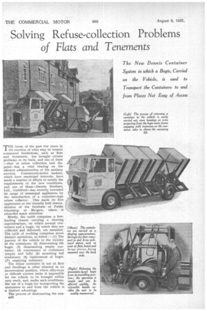
The New Dennis Container System in which a Bogie, Carried on the Vehicle, is used to Transport the Containers to and from Places Not Easy of Access
THE boom of the past few years in the erection of what may be termed communal habitations, such as flats and tenements, has brought certain problems in its train, and one of them —that of refuse collection and disposal—has a vital bearing on the efficient administration of the sanitary services. Commercial-motor makers, which have municipal interests, have made a number of efforts to satisfy the requirements of the new conditions, and one of them—Dennis Brothers, Ltd., Guildford—has recently extended its range of municipal appliances by the introduction of a container-type refuse collector. This made its first appearance at the recently held demonstration of the Institute of Public Cleansing, at Margate, where it attraded much attention.
Briefly, the outfit comprises a lowloading chassis carrying a slanting superstructure, on which several containers and a bogie, by which they are collected and delivered, are mounted. The cycle of working comprises seven distinct operations, as follow :—(1) The journey of the vehicle to the vicinity of the containers; (2) dismounting the bogie; (3) dismounting empty container; (4) conveyance of containers (empty and full); (5) mounting full containers; (6) replacement of bogie; (7) emptying container.
The refuse container in use at flats and dwellings is often situated in an inconvenient position, where alleyways or difficult corners make it impossible for the vehicle to be brought within easy reach, and, under such conditions, the use of a bogie for transporting the containers to and from the vehicle is a distinct advantage.
The process of dismounting the conB36 tainers from the chassis is a straightforward operation. A handle, engaging on a square spigot at the rear, drives, through reduction chain gearing, a longitudinal shaft at the top of the container tracks. To allow for flexing of the chassis when operating on rough ground, this shaft is in three sections, with two universal joints, whilst its bearings are spherically seated, Four dog clutches, each controlled by a separate lever, enable power to be .transmitted to one or more of the reels on Which the container cables are mounted. Spring-loaded ball catches prevent the free movement of the reels when the clutches are disengaged.
The operator's first action is to raise one of the -empty containers a few inches. This actuates a trip lever for the automatic safety catch supporting the container,' so that, when this has "clicked," the handle action may be .reversed and the container lowered. Before the container reaches the end of its travel the trip gear must again be ' operated, after which the container can be lowered to the ground, when it auto
matically assumes an upright position as the cable is slacked off.
For easy handling of the dismounted container the two-wheeled bogie carried over the rear axle is employed. This is easily brought into action by disconnecting two spring-loaded catches that secure its retaining bar, which, when released, enables it to descend on its own runway. The actual raising cif the container from the ground is effected by the simplest of leverages.
Trunnions, located on the side of the container slightly above its centre of gravity, engage with open housings at the extremities of two arms which project from the main frame.. The bogie is replaced on its carrier by reversing the process by which it was removed.
, Returning the Container.
When it is desired to return a loaded container -to the vehicle,. the cable is attached to a hook at the top of the container body and, as the handle is turned, so the bin is tilted, drawn into correct alignment with the guide rails and then brought into position.
As it ascends the superstructure, the upper of the two bars on. the underside enuages with the locking gear, setting it ready for the reception of the lower bar, which actually supports the load.
On arrival at the tip, one or more of -the containers can be emptied simultaneously. Each container has a capacity of 4 cubic yd., although this figure can be altered to requirements.
The standard container is .5 ft. 6 ins. . high, .2 ft., 8 ins.. wide and4. ft. &iris: long. It is built of .galvanized plates_on .an angle-iron frame and, to. facilitate .the..discharge.. of the contents, is .tapered 4 in.. from .top to.hottom. The . whole of one end of the, container camprises a doOr, which, has a rubber seal.
The basis of the outfit is a forwardcontrol • chassis,' with the front axle 'set' well back so .as to give a short wheel-base (11 ft 6 me.), with acorrespondingly small turning circle .(41. ft.),
• Theaarrie .principle. can, _of course, -be applied to an articulated six-wheeled chassis, whilst a further variation con-.
• sists of 'a trailer carrying: .the. entire 'container gear, for use with atractor.