German Fast Road-train 7 ,
Page 30

If you've noticed an error in this article please click here to report it so we can fix it.
Developments
AS a natural sequence to the construction in Germany of high-speed arterial roads comes the fast transport of really heavy loads by their means. The development of special types of vehicle for this purpose has now assumed in that country a position of considerable importance.
An example of one line along which investigations are being made is the Kamper train, now be,ing subjected to test. Loads of up to 60 tons can be hauled by this system, one tractive unit being capable of providing adequate motive power for the requisite high speeds to be maintained. The fact that the necessary personnel comprises only two men is by no means a trifling incidental consideration.
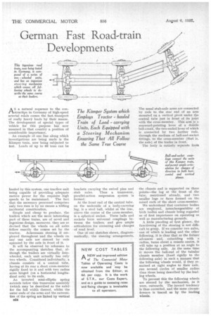
Simple and cheap to produce, the trailers which are the more interesting part of these trains, are of novel and ingenious design, moreover, they are so devised that the wheels on All axles • follow exactly the course set by the tractor. Ackermann steering if em • ployed throughout and the wheels on any one axle are steered by rods operated by the axle in front of it. It will be observed by reference to the accompanying sketches that, although the trailers are virtually fourwheeled, each unit actually has only two wheels. Considered individually, a chassis consists of, a central tube, having at its rear a short cross-member rigidly fixed to it and with two radius • arms hinged (on a horizontal longitudinal axis) to its ends.
An inverted semi-elliptic spring extends belew this transverse assembly (which may be described as the axle) for the full width thereof, whilst the outer ends of the arms and the extremities of the spring are linked by vertical
D24 brackets carrying the swivel pins and stub axles. Thus • a transverse, parallel-action suspension system is formed: At the front end of the central tube. on the underside of a body-carrying lug, is a steel ball, whilst at the rear, above the centre of the cross-member, is a spherical socket. These balls and sockets form universal couplings between the trailers, and give ample articulation for cornering and changes of road level.
One of our sketches shows, diagrammatically, the steering arrangements. The usual stub-axle arms are connected by rods to the rear enl. of an arm mounted on a vertical pivot under the central tube just in front of its joint with the cross-member. This arm is a rearward-pointing lever of a double bell-crank, the two-ended lever of which is connected by two further rods, through the medium of ball-and-socket fittings, to the cross-member (that is, the axle) of the trailer in front.
The body is entirely separate from the chassis and is supported on three points—the lug at the front of the tube, mentioned already, and two smaller lugs or faces formed on the raised ends of the short cross-member.
We understand that container bodies are employed, interchangeability of both bodies and chassis being regarded as of first importance on operating as well as manufacturing grounds.
• A little puzzling at first glance, the functioning of the steering is not difficult to grasp. If we consider two axles, one of which is leading and the other following, it is clear that as the former advances and, coinciding with a radius, turns about a remote centre, it will take up a position at an angle to the following axle. At the same time it 'moves the ball-end of the tubular chassis member (fixed rigidly to the following axle) in such a manner that the -following wheels would, if they remained at right angles to their axle, run around circles of smaller radius than those being described by the leading wheels.
To prevent this the following wheels are steered by the mechanism, as it were, outwards. The inward tendency is thus corrected, and the same circumference is traced as by the leading wheels.


