


A Miscellany, of
Page 72
If you've noticed an error in this article please click here to report it so we can fix it.
NEW PATENTS
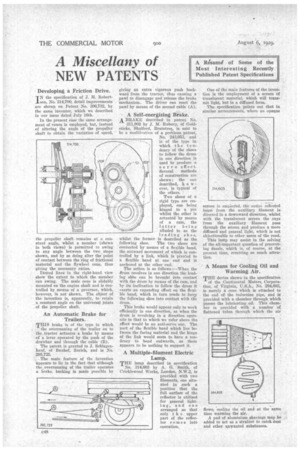
Developing a Friction Drive.
IN the specification of J. H. Robert8On, No. 314,700, detail improvements are shown on Patent No. 306,732, by the same inventor, which we described in our issue dated • July 16th. .
In the present case the same arrangement of cones is employed, but, instead of altering the angle of the propeller shaft to obtain the variation of speed, the propeller shaft remains at a constant angle, whilst a member (shown in both views) is permitted to swing to any angle between the two stops shown, and by so doing alter the point of contact between the ring of frictional material and the flywheel cone, thus giving the necessary ratios.
Dotted lines in the right-hand view show the extent to which the member can 'swing. The male cone is slidably mounted on the engine shaft and is Controlled by means of a governor, which, however, is not shown. The object of the invention is, apparently, to retain a constant angle on the universal joints of the propeller shaft.
An Automatic Brake for Trailers.
THis brake is of the type in which . the overrunning of the trailer on to the, tractor actuates a brake by means of a lever operated by the push of the drawbar and through the cable (B).
The patent is granted to J. Schlagenhauf, of Bauhof, Zurich, and is No. 295,725. The main feature of the invention appears to lie in the fact that although the overrunning of the trailer operates a brake, backing is made possible by giving an extra vigorous push backward from the tractor, thus causing a pawl to disengage and release the brake mechanism., The driver can reset the pawl by means of the second cable (A).
A Self-energizing Brake. A BRAKE deseribed in patent. No.
311,902 by J. M: Ruhury, of .Goldsticks, .Shalford, Braintree, is said to be a modification of a previous patent, No. 243,053, and is of the type in which the to iidency of the shoes to follow the drum in one direction is used to produce servo effect. Several methods of construction are shown ; the one described, h o w ever, is tyPical of the others. : Two shoes of a rigid type are employed, one being hinged to' a pin whilst the other is actuated 'by means of a cam, the latter being alluded to as the leading shoe, whilst the former is described as the
following shoe. The two shoes are connected by means of a flexible band, the outward movement of which is controlled by a link, which is pivoted to a flexible band at one end and is anchored at the other end.
The action is as follows ;—When the drum revolves in one direction the leading shoe can be brought into contact with the drum by means of the cam, and by its inclination to 'follow the drum it exerts an expanding effect on the flexible band, which in turn tends to force the following shoe into contact with the drum.
This brake would appear only to work efficiently in one direction, as when the drum is revolving in a direction opposite to that to which We refer above the effect would be an anti-servo one. The part of the flexible band which lies between the facing material and the hinge of the link would seem to have a tendency to bend outwards, as there appears to be nothing to support it.
A Multiple-filament Electric Lamp.
THE lamp described in specification No. 314,603 by A. G. Smith, of Cricklewood Works, London, N.W.2, is provided with two filaments, one situated in such a position that the full surface of the reflector is utilized for general lightn g , and one arranged so that only t h e upper part of the reflector comes into operation. One of the main features of the invention is the employment of a screen "of translucent material, which will transmit light, but in a diffused form. The specification points out that in similar arrangements, where an opaque
screen is employed, the entire t7e-fitTeted beam from the nazi iary filament is directed in a downward direction, whilst with the translucent screen the rays from the auxiliary filament pass through the screen and produce a more diffused and general light, which is not objectionable to other users of the road.'
This lamp may assist in the solving of the all-important question of preventing dazzle, which is, of course, at the present time, receiving so much attention.
A Means for Cooling Oil and . Warming Air.
THE device shown in the specification of the Continental Motors Corporation, of Virginia, 17.8.A., NO. 294,603, is merely a cone which is attached to the end of the induction pipe, and is Provided 'with a chamber through Which passes the lubricating oil. This chamber is provided with a number of flattened tubes through which the air flows, "cooiing, the oil and at the same time warming the air..
A A pad of aluminium shavings ,may he added to act as a strainer to catch dust and other unwanted substances.