


An Effective Design of
Page 62
If you've noticed an error in this article please click here to report it so we can fix it.
Destination opm, PEFipc-roR. SITNCIL
Indicator
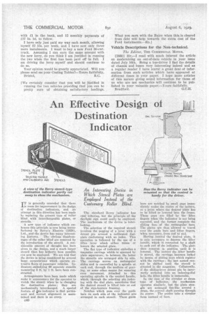
IT is generally conceded that there is room for improvement in the design of destination indicators, and an attempt in this direction has been made by replacing the present type of roller blind with interchangeable plates, or stencils.
A new type of indicator which embraces this principle is now being manufactured by Berry's Electric (1928), Ltd., „and -the device has many interest ing features. The obvious disadvantages of •the roller blind are removed by the introduction• of the stencil. A considerable amount of thought has been given to the design, and a much larger stencil than has hitherto been possible can now be employed. We are told that the device is being considered by several large corporations which operate extensive fleets of passenger vehicles. Indicators embodying 60 separate stencils measuring 5 ft. by 1 ft. have been con
structed. '
Arrangements have been made which make it unnecessary for the operator to watch the stencil when he is changing the destination plates; they are mechanically interchanged. A special feature of Oda indicator is that permanent and correct alignment is maintained and there is no creep.
c40
The standard Berry indicator has opal lettering, but the principle of the daylight sign could easily be employed. The mechanism of the device is interlocking.
The selection of the required stencil involves the pegging of a lever with a detent pin around a calibrated dialplate conforming with an index. This operation is followed by the use of a lifter • lever which either raises or lowers the selected plate.
The fiat type of indicator embodies a magazine carriage whichis spanned by plate separators ; in between the latter the stencils are arranged side by side. The carriage moves on rectangular slides and is controlled by a spindle at each end, through the medium of gearing, or some other means for ensuring even movement Attached to this operating spindle is the control handle, which, through the 'selecting pin indexing with the dial plate,ascertains that the desired stencil is lifted into or out of the sign-lantern framing.
Notches which pass over the guide bars on each side of the indicator are. arranged in each stencil. These guide
bars are notched by small gaps immediately under the centre of the lantern, at' a point where the desired plate has to be lifted Or lowered into the frame. These gaps are filled by the' :liftet fingers when the indicator is not being operated, and the former complete the sliding face of the rectangular bars. The plates are thus allowed to travel over the guide bars and lifter fingers, When necessary, from end to end.
Having located the desired plate, it is only necessary to depress the lifter handle, which is connected by a shaft to each end of the indicator. The plate then remains in position -until it is lowered. The instant the lifterhandle is moved, the carriage becomes looked by means of sliding. keys which register with the carriage; the last named cannot be shifted until the stencil is situated in the magazine. Collaterally, if the sliding-lever detent pin be incorrectly socketed into an indexing-dial hole, the lifter handle is immovable.
In the case of the circular or drum type of indicator, the mechanism operates similarly. but the plate stenfidls are arranged fan-like around a drum, the control shaft passing through its centre. The guides take:a eirdular form instead of bars.