External Control in
Page 27

If you've noticed an error in this article please click here to report it so we can fix it.
New Dampers AALTERATIONS to their characteristics by external means are possible in the new Spax range of hydraulic telescopic dampers introduced by J. 1-1. Sankey and Soo, Ltd„ Aldwych House, Aldwych, London, W.C.2. The adjustment can quickly be made either on the outside of the damper or from the dashboard of the vehicle.
On normal telescopic dampers the valve assembly is inside the piston, and consists of spring-loaded laminated plates, or blow-off taper-head valves. Any device to adjust these would have to be inside the pressure tube and move up and down with the piston, but the operating mechanism would at some point have to pass out of the pressure tube, involving a complicated sealing system.
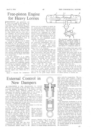
The control valve on the new Spax damper is at the top, in the oil-seal and piston-rod guide assembly, instead of in the piston. Fluid that has been compressed on the upward or rebound stroke passes through the valve and into the top of the reserve chamber, which is in the form of a jacket surrounding the main pressure chamber. From here it passes over anti-frothing or aeration baffles, and falls through the air space into the base of the reserve chamber.
Consequently, fluid that has been compressed and suffered a sharp rise in temperature cannot return to the
pressure chamber until it has had a period for cooling. When it does do so it comes through a foot-valve assembly at the bottom of the unit. The piston is of simple design, incorporating only a valve for recuperation. The new fluid control valve contains a Spaxamatic control disc, which is fitted in the head of a spring-controlled valve. At slow speeds the compressed fluid from the main chamber will pass through the Control disc before dropping into the reserve chamber.
At high speeds, when the control disc is fully loaded by virtue of the controlled velocity of filtration, the whole of the valve assembly lifts from its seating and permits a free flow of fluid to the reserve chamber. The damper never suffers from a " solid " position so that high temperatures cannot be reached.
The •adjustment mechanism is on the outside wall of the reserve chamber, in line with the high-speed valve, where it is not pressurized or subject to leakage of fluid. It comprises a small assembly, where by means of a projecting screw the tension of the spring controlling the high-speed valve may be adjusted, and so alter the characteristics of the unit without removing it from the vehicle.
This is most useful when the vehicle is being used over changing varieties of road and load conditions. If dashboard control is required this may be carried out by sheathed cables, or by hydraulic or vacuum systems, at the discretion of the manufacturer.


