


A Pneumatic Coupling
Page 68
If you've noticed an error in this article please click here to report it so we can fix it.
A Resume of Recently Published Patent Specifications
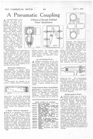
A CONTRIVANCE which PI may be used for a number of purposes is described in patent No. 406,374, by P. W. Forrest, Vine Terrace, Shields Road, Motherwell, and J. H. Stephen, Anchorage, 1,783, Shettleston Road, Glasgow.
The basis of the invention is the coupling of two members by inflating a pneumatic tyre between them. This, it is claimed, may be used to unite two shafts resiliently, whether rotary or stationary, and may be used to couple ft spring shackle to its chassis, thus forming a shockabsorbing device.
The drawing shows its application as a shaft coupling, the inner member being in the form of a rim, whilst the outer 'member is concave and fits the
tyre closely. Apart from its flexibility, this invention appears to us to offer interesting possibilities in the way of quick assembly and removal, the processes of inflation and deflation taking the place of assembling or removing nuts and bolts.
'Brake-drum Modifications.
ACCORDING to Sydney Smith, Dingley Dell, Windlesham Road, Chobham, Surrey, many brake troubles are due to the retention of foreign matter in the brake drums. This may consist of oil, grease or road grit, with an admixture of disintegrated brake lining.
In his patent. No. 406,347, he describes a simple method of keeping a drum clear of all these undesirable substances. The method is to drill a number of holes in the brake drum, so spaced that every portion of the lining is uncovered for a moment. To prevent the entrance of large quantities of water and mud a light cover is provided around the periphery of the drum.
A 'Simple Track-rod Adjustment.
FROM E. B. Boughton, W. Emmott and D. T. Brock, trading as Automotive Products Co., Brock House, Longhorn Street, London, W.I, comes patent No. 406,438, describing an extremely simple means for adjusting steering track rods. The method employed is to make the spherical head of the pin eccentric with respect to its conital seating. The illustration shows clearly the scheme, which, _.it • is claimed, is of particular application `to
n50 existing vehicles, the ordinary pins being removed, and these special eccentric pins inserted. Thus, at a small expense, an adjustable trackrod is obtained.
An Anti-freezing Device, A SIMPLE attachment for the pre vention of freezing is shown in patent No. 406,044, by J. Knott, 30a, Sedgemore Avenue, London, N.2, and WI F. Tipping, 13, Valley Drive, London, N.W.9. The drawing shows the suggesked scheme ; a tubular member containing a resistance element is inserted in the circulation system of the engine. For heating a cold engine, it is suggested that the heater be con.nected to the mains, although, in emergencies, to prevent the water freezing in the open, the device may be run from the accumulator on the vehicle, a duplex winding being provided.
Totally Enclosed Brake Compensation.
TMPROVED compensation of four-.
wheel brakes forms the subject of patent No. 405,734, by Ethel Alice Johns. "The Hutt," Rushden, Northants. Several forms of construction are described, one of which we
illustrate. The whole gear is contained in an .oiltight casing, glands being provided around the operating rods. Water, grit and other dele
terious matter being thus excluded, the apparatus should work smoothly under all conditions.
In the drawing, the rod which has the pedal or servo motor attached is shown with a spring around it, the other four rods each being connected to a brake. The central pivot of the large lever is adjustable in a lengthwise direction for the purposes of taking up wear. The compensating movement can easily be understood from the arrangement of the levers.
Equal forces are transmitted by the two ends of the master balance bar, and similarly by those of the front and rear rocking beams. To apply greater power to the rear brakes the central pivot of the long lever must be moved upwards.
Bumper-operated Brakes.
ADEVICE which may be used to operate brakes, ignition, or both, is described by C. D. Terry, 141, Russell Road, Moseley, Birmingham, in patent No. 406,352. The invention consists of a special form of bumper which is constructed so that an impact closes an electric circuit.
Several schemes are illustrated, the underlying principle being that of two parallel wires held apart by compressible supports, which, in the event of a collision, would be overcome. If brakes are to be applied by this method, then they must be electrically operated; the ignition system needs little modification to enable it to be controlled by apparatus of this type. Whilst devices of this kind may be use, ful in preventingofire after an accident, . to apply the brakes at the moment of , impact would do little to minimize the damage.