


A New Moderate-capacity Crossley Oil Engine
Page 42
Page 43
If you've noticed an error in this article please click here to report it so we can fix it.
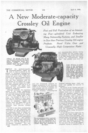
First and Full Particulars of an Interesting Four cylindered Unit Embracing Many Noteworthy Features, and Smaller in Size than Previous Crossley Oil-engine Products. Novel Valve Gear and Unusually High Compression Ratio
THAT the moderate-capacity compression-ignition engine has come to stay is proved by the number of prominent manufacturers which is interested in or actually producing such power units. The latest convert to the type is Crossley Motors, Ltd., Gorton, Manchester —a concern that has been associated with the manufacture of oil engines for a very long time. The new engine is a 3.620litre four-cylindered unit and is to be made alongside the larger fourcylindered and six-cylindered types already in production.
Although, naturally, the experience gained in the design, manufacture and maintenance of the larger models has been fully utilized, the new engine, in many ways, strikes quite a new note. An example of this is to be found in the method of valve operation which is novel and possesses the virtue of simplicity. Again, the cylinder block and, upper half of the crankcase are formed as a unit—a departure from previous Crossley practice.
As will be seen from accompanying illustrations, it has distinctive and clean lines, the oil side being clear of all components likely to require adjustment during service, so that no installation difficulty should be experienced due to the special requirements
of forward control-. The cylindercrankcase casting is really substantial, with webs running right across the interior to carry the journals of the five-bearing crankshaft. The lastnamed component is machined all
E24 over and dynamically balanced by weights incorporated in the stamping, whilst in the interests of accuracy the main journals and the crankpins are ground and finished by lapping.
Forged H-section connecting-rods and aluminium-alloy pistons, having four pressure and two scraper rings, are employed, the gudgeon-pins being of the fully floating type and located endwise by deep-sectioned spring clips. The cylinder bores have air hardened cast-iron liners, which can easily and quickly be removed if necessary. • The layout of the cylinder head and the valve mechanism next claim attention. The camshaft lies alongside the cylinder bores and is . situated just below the machined surface on to which the head is bolted, . There are eight rectangular holes cored in the top face, to allow the cam followers (incorporated in the cylinder head) to reach • the cams, the reciprocating motion being transmitted to the valves by means of unusually short push-rods and rockers—a neat and extremely simple arrangement. The camshaft itself is rotated by a triple roller chain from the crankshaft, an automatic tensioning device being incorporated in the layout.
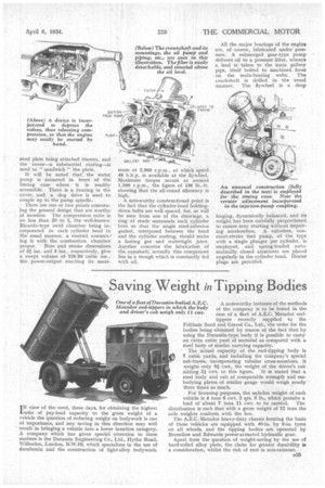
On the off side of the engine are the dynamo and water pump, both of which are driven from one shaft. The injection-pump and governor drive is
on the near side of the unit. In this connection, the design of the timinggear cover may be mentioned. In the first place the end of the cylindercrankease casting is machined flat, a
steel plate plate being attached thereto, and the cover—a substantial casting—is used to " sandwich theplate.
It will be noted that, the water pump is mounted in front of the timing case where it is readily accessible. There is a bearing in the cover, and a dog drive is used to couple up to the pump spindle.
There are one or two points concerning the general design that are worthy of mention. The compression ratio is no less than 20 =to 1, the well-known Ricardo-type swirl chamber being incorporated in each cylinder head in the usual manner, a venturi connecting it with the combustion chamber proper. Bore and stroke dimensions of 3* ins. and 5 ins., respectively, give a swept volume of 220.89 cubic ins., the power-output reaching its maxi
mum at 2,000 r.p.m., at which speed 48 b.h.p. is available at the flywheel. Maximum torque occurs at around 1,200 r.p.m., the figure of 136 lb.-ft. showing that the all-round efficiency is high.
A noteworthy constructional point is the fact that the cylinder-head holdingdown bolts are well spaced, for, as will be seen from one of the drawings, a ring of studs surrounds each cylinder bore so that the single steel-asbestos gasket, interposed between the head and the cylinder casting, should make a lasting gas and watertight joint. Another concerns the lubrication of the camshaft; actually this component lies in a trough which is constantly fed with oil.
All the major bearings of the engine are, of course, lubricated under pressure. A submerged gear-type pump delivers oil to a pressure filter, whence a lead is taken to the main gallery pipe, itself bolted to machined faces on the main-bearing webs. The crankshaft is drilled in the usual manner. The flywheel is a drop
forging, dynamically balanced, and its weight has been carefully proportioned to ensure easy starting without impairing acceleration. A valveless, constant-stroke fuel pump, of the type with a single plunger per cylinder, is employed, and spring-loaded automatically closed atomisers are placed angularly in the cylinder head. Heater plugs are provided.