


An Exhaust-gas Purifier
Page 68
If you've noticed an error in this article please click here to report it so we can fix it.
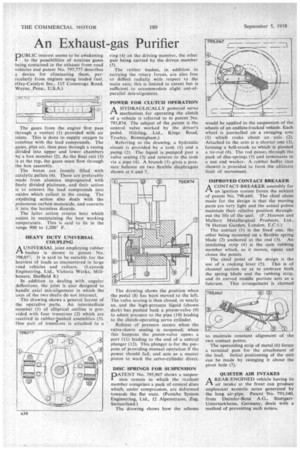
13111 UBLIC interest seems to be awakening I to the possibilities of noxious gases being contained in the exhaust from road Vehicles and patent No. 797,777 describes a device for eliminating them, particularly from engines using leaded fuel. (Oxy-Catalyst Inc., 115 Conestoga Road, Wayne. Penn., U.S.A.) The gases from the engine first pass through a venturi (1) provided with air inlets. This is done to supply oxygen to combine with the lead compounds. The gases, plus air, then pass through a casing divided into upper and lower chambers by a box member (2). As the final exit (3) is at the top, the gases must flow through the box assembly.
The boxes are loosely filled with catalytic pellets (4). These are preferably made from alumina impregnated with finely divided platinum, and their action is to convert the lead compounds into oxides which collect in the casing. The oxydizing action also deals with the poisonous carbon monoxide, and converts it into the harmless dioxide.
The latter action creates heat which assists in maintaining the best working temperature. This is said to lie in the range 900 to 1,200° F.
HEAVY DUTY UNIVERSAL COUPLING
AUNIVERSAL joint employing rubber bushes is shown in patent No. 798,077. It is said to be suitable for the heaviest of loads as encountered in large road vehicles and railcars. (Laycock Engineering, Ltd., Victoria Works, Mill
houses, Sheffield 8.) •
In addition to dealing with, angular deflections, -the joint is also designed to handle axial mis-alignment in which the axes of the two shafts do not intersect.
The drawing shows a general layout of the operative parts. An intermediate member (1) of elliptical outline is provided with four trunnions (2) which are received in rubberlushed assemblies (3). One pair of trunnions is attached to a ring (4) on the driving member, the other pair being carried by the driven member (5).
The rubber bushes, in addition to carrying the rotary forces, are also free to deflect radially with respect to the main axis; this is limited in extent but is sufficient to accommodate slight out-ofparallel m is-al ignment.
POWER FOR CLUTCEI OPERATION A HYDRAULICALLY powered servo I-1 mechanism for operating the clutch of a vehicle is referred to in patent No. 795,874. The subject of the patent is the control valve worked by the driver's pedal. (Girling, Ltd., Kings Road, Tyseley, Birmingham.) Referring to the drawing, a hydraulic circuit is provided by a tank (1) and a pump (2). The liquid is pumped past a valve seating (3) and returns to the tank via a pipe (4). A branch (5) gives a pressure,balance on two flexible diaphragms shown at 6 and 7.
The drawing shows the position when the pedal (8) has been moved to the left. The valve seating is then closed, or nearly so, and the high-pressure liquid (shown dark) has pushed back a piston-valve (9) to admit pressure to the pipe (10) leading to the clutch-operating servo cylinder.
Release of pressure occurs when the valve-sleeve seating -is reopened; when this happens the piston-valve opens a port (11) leading to the end of a central plunger (12). This plunger is for the purpose of providing manual operation if the power should fail, and acts as a master piston to work the servo-cylinder direct.
DISC SPRINGS FOR SUSPENSION DATENT No. 795,967 shows a suspension system in which the resilient member comprises a pack of conical discs which, under compression, are deformed towards the flat state. (Porsche System Engineering, Ltd., 12 Alpenstrasse, Zug, Switzerland.)
The drawing shows bow the scheme
would be applied to the suspension of the wheels of an endless-tracked vehicle. Each wheel is journalled on a swinging arm (1) which rocks about an axis (2). Attached to the arm is a shorter one (3), forming a bell-crank to which is pivoted a tie-rod (4). The rod passes through the pack of disc-springs (5) and terminates in a nut and washer. A rubber, buffer (not shown) is provided to form the.ultirnate .limit of movement.
IMPROVED CONTACT BREAKER A CONTACT-BREAKER assembly for ris an ignition system forms the subject of patent No. 798,660. The chief claim made for the design is that the moving parts are very light and the actual points maintain their relative position throughout the life of the unit. (F. Hooven and Mallory Metallurgical Products, Ltd.,• 78 Hatton Garden, London, E.C.1.)
The contact (1) is the fixed one, the other being mounted on a flexible spring blade (2) anchored at the end (3). An insulating strip (4) is the cam rubbing member Which, as it moves, opens and closes the points.
The chief point of the design is the use of a rocking lever (5). This is of channel section so as to embrace both the spring blade and the rubbing strip, and its curved middle portion acts as a fulcrum. This arrangement is claimed to maintain constant alignment of the two contact points.
The upstanding strip of metal (6) forms a terminal post for the attachment of the lead. Initial positioning of the unit can be made by swinging it about the pivot hole (7).
QUIETER AIR INTAKES
AREAR-ENaINED vehicle having its air intake at the front can produce unpleasant acoustic notes generated by the long air-pipe, Patent No. 793,340, from Daimler-Benz A.G., StuttgartUnterturkheint, Germany, deals with a method of preventing such noises.