


Carrimore Build Four-pillow Air Suspension Bogie
Page 49
If you've noticed an error in this article please click here to report it so we can fix it.
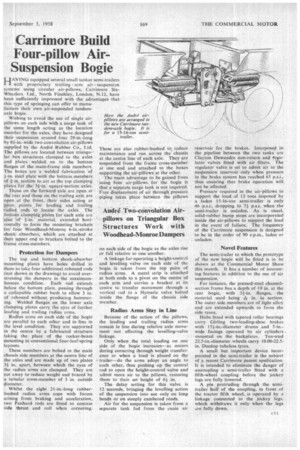
HAVING equipped several small tanker semi-trailers with proprietary trailing arm air suspension systems using circular air-pillows, Carrimore SixWheelers _ Ltd., North Finchley, London, N.12, have been sufficiently impressed with the advantages that this type of springing can offer to manufacture their own air-suspended tandemaxle bogie.
Wishing to avoid the use of single airpillows on each side with a surge tank of the same length acting as the location member for the axles, they have designed their suspension around four 29-in.-long by 84-in.-wide two-convolution air-pillows supplied by the Andre Rubber Co., Ltd.
The pillows are located between triangular box structures clamped to the axles and plates welded on to the bottom flanges of the main-frame side members. The boxes are a welded fabrication of
+-in. steel plate with the bottom. members. of fin. section to act as the top clanaping. plates for the' Win. square-section 'axles.
Those on the forward -axle are open at -the rear and those on. the' trailing axle are open at the front, their• sides. acting as pivot points for leading and trailing faeliuS rods to locatethe axleS. The
bottom clamping, plates for each axle are also of fin.material, extendedhorizontally to form the mounting brackets for four Woodhead-Monroe 6-in.-stroke shock absorbers, which are attached at their upper end to brackets bolted to the frame cross-members.
Protection for Dampers
The top and bottom shock-absorber mounting plates have holes drilled in them to take four additional rebound rods (not shown in the drawing) to avoid overstressing the dampers in the maximumbounce condition. Each rod extends below the bottom plate, passing through a collapsible rubber bush to allow 3 in. of rebound without producing hammering. Welded flanges on the lower axle clamping plates carry the eyes of further leading and trailing radius arms.
Radius arms on each side of the bogie are parallel to each other and in line in the level condition. They are supported in the centre by a fabricated structure taking the place of the rocker-beam mounting in conventional four-leaf-spring layouts.
These members are bolted to the main chassis side members at the centre line of the axles and are made up of two plates 3+ in, apart, between which the eyes of the radius arms are clamped. They are cut away to reduce weight and braced by a tubular cross-member of 3 in. outside diameter.
Whilst the eight 21-in.-long rubberbushed radius arms cope with forces arising from braking and acceleration, two Panhard rods are fitted to contain side thrust and roll when cornering. These are also rubber-bushed to reduce maintenance and run across the chassis at the centre line of each axle. They are suspended from the frame cross-member at one end and attached to the boxes supporting the air-pillows at the other.
The main advantage to be gained from using four air-pillows for the bogie is that a separate surge tank is not required. Free displacement of air through pressure piping takes place between the pillows on each side of the bogie as the axles rise or fall relative to one another.
A linkage for-operating a height-control and levelling valve on each side of the bogie is taken from the top pairs of radius arms. A metal strip is attached at both ends to a pivot on the centre of each arm and carries a bracket at its centre to transfer movement through a vertical iod to a Hymatic valve bolted inside the flange of the chassis side member,
Radius Arms Stay in Line
Because of the action of the pillows, the leading and trailing radius arms remain in line during relative axle movement not affecting the levelling-valve Only when the total loading on one side of the bogie increases—as occurs during cornering through weight transference or when a load is placed on thp trailer—do the arms adopt an angle to each other, thus pushing up the central rod to open the height-control valve and admit more air to the pillows, restoring them to their set height of 64in.
The delay setting for this valve is 12 seconds, bringing the levelling action of the suspension into use only on long bends or on steeply cambered roads.
Air for the suspension is taken from a separate tank fed from the ,nain air reservoir for the brakes. Interposed in the pipeline between the two tanks are Clayton Dewandre non-return and fegulator valves fitted with air filters. The regulator valve is set to admit air to the suspension reservoir only when pressure in the brake system has reached 65 p.s.i., thus ensuring that brake operation will not be affected.
Pressure required in the air-pillows to support the load of 13 tons imposed by a laden 15-16-ton semitrailer is only 46 dropping to 71 psi. when-the semi-trailer is unladen. As is usual, solid-rubber bump stops are incorporated inside the air-pillows to support the load in the event of failure. The frequency of the Carrimore suspension is designed to be in the order of 90 c.p.m., laden or unladen.
Novel Features
The semi-trader to which the prototype of the new bogie will be fitted is to be shown at the Commercial Motor Show this month. It has a number of interesting features in addition to the use of air suspension.
For instance, the pressed-steel channelsection frame has a depth of 19 in. at the rear bogie, with 31-in. flanges, the material used being in. in section. The outer, side members are of light alloy and are extended upwards to form the side raves.
Hulas fitted with tapered roller bearings carry Girling two-leading-shoe brakes with 154-,in.-diameter drums and 5-inwide facings operated by air cylinders mounted on the backplates. Ten-stud 22.5-in.-diameter wheels carry 10,00-22.5in, Dunlop tubeless tyres.
A small but important device incorporated in the semi-trailer is the subject of a recent Carrirnore patent apolitation. It is intended to eliminate the danger of uncoupling a semi-trailer fitted with a fifth wheel coupling before the jockey legs are fully lowered.
A pin protruding through the semitrailer half of the coupling, in front of the tractor fifth wheel, is operated by a linkage connected to the jockey legs, which withdraws it only when the legs are fully down.