


Roller Clutch to Replace Hand-brake Ratchet
Page 34
If you've noticed an error in this article please click here to report it so we can fix it.
A Resume of Recently Published Patent Specifications
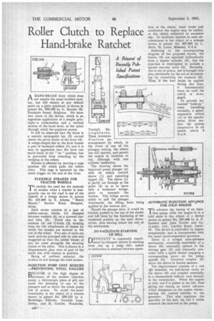
AHAND-BRAKE lever which does not require the usual toothed rackbar, but will remain at any delired point on a plain quadrant, is shown in patent No. 538,106 by G. Hunter: 62, 'Frederick Street. Brighton, We show two views of the device, which is an ingenious application of a simple principle—a cross-section and a vertical section of the hand lever, at the point through which the quadrant passes.
It will be ebserved that the latter is a smooth rectangular bar (3) curved about the pivot centre of the lever (4). A wedge-shaped slot in the lever house's a pair of hardened rollers (1) and it is easy to appreciate how the lever can move freely to the "on " position, but is prevented from returning by the wedging of the rollers.
Release is effected by moving a cage member (2) which pulls the rollers dear. This cage is operated by the usual trigger on the end of the !ever.
FLEXIBLE STRAKES FOR TRACTOR WHEELS
'Prabolish the.need for the removal of strakes when a tractor is temporarily run on the road is one of the objects of a design shown in patent No. 637,890 by E. Adams, "Beech Mount," Station Road, Newport, Salop.
Each stroke consists of a pair of rubber-canvas blocks (I) clamped between washers (4) on a screwed central tube (3). Fixed also to the washers (4) are U-bolts (2) forming links for the attachment of chains by which the strokes are secured to the rim of the wheel. Two sets of units are used, and are arranged side by side and staggered so that the, rubber blocks of one set come alongside the securing chains of the other. This is shown in a diagrammatic plan view of part of the wheel rim with strokes in position.
Being of resilient material, the strakes do not damage the road surface.
INJECTION PUMP UNIT SEIZURE —PREVENTING TOTAL FAILURE
BECAUSE of the high degree of accuracy of the modern injection pump, a microscopic piece of grit can cause the jamming of one of the plungers and so throw the whole pump out of action. To avoid the latter eventuality is the object of a scheme shown in patent No. 538,1'33 by A. Rowledge, Eilerslie, Trowells Lane, Derby, and R. Corbitt, Woodville,
A32' Twister". Sittingbourne. These inventors disclose an arrangement by which, in the event of one of the plungers seizing, the others can still operate, and permit the engine to continue to run, although with one cylinder ineffective. The drawing shows the improved pump plunger (4) with its rotary control sleeve (1) and operating tappet (2). The sleeve (1) is partly cut through at the point (3) so as to leave only a weakened bridgepiece to transmit the motion. This bridge serves solely to pull the plunger downwards, the lifting force applied •to the bottom end. Should the plunger seize, it would be forcibly pushed to the top of the stroke and left' there by the fracturing of the weakened portion on the next downstroke, thus leaving intact the rest of the mechanism, being .TO FACILITATE STARTING UP HILL
DIFFICULTY is commonly experi1-fenced by inexpert drivers in starting from rest up a steep' hill ; unless co-ordination is attained between opera
tion of the clutch, band brake and accelerator the engine may be stalled, or the clutch subjected to excessive slip. To facilitate matters in such circumstances is the abject of a scheme shown in patent No. 537,956 by L. Betts, St. Louis, Missouri, U.S.A.
Referring to the accompanying diagram of the proposed layout, the brakes (2) are operated hydraulically from a master cylinder (4), but the pipe-line is interrupted to include a special one-way valve (3). Normally. this is out of action, but is brought into play electrically by the act of de-clutching 'by connecting the contacts (5). Thus, if the foot brake be applied during this time, it automatically stays on until the clutch is re-engaged.
To prevent unwanted "hold-on "
when travelling normally, a speedresponsive switch (1), in the speedometer drive renders the system inoperative at all speeds above 2 m.p.h.
AUTOMATIC INJECTION ADVOCE FOR COLD ENGINE
TO advance tbe timing of an injection pump while the engine is in a 'Cold state is the object of a device shown in patent No. 537,958 by A. F. Sanders and John Fowler and Co. (Leeds), Ltd., Leathly Road, Leeds. 10. The device is controlled by engine temperature, and is incorporated with the usual speed-responsive governor.
There is a normal auto-advance mechanism, consist* essentially of a sleeve (4), externally splined to the driving gear (2) and internally provided with a quick thread engaging a corresponding screw on the pump spindle (3). Governor weights (5) move the sleeve in known manner.
The irnprovernent consists of a rod (0) attached, via ball-thrust races, to the sleeve (4) and coupled externally to a thermostatic bellows (not shown) in the waterjacket. When the engine is cold, rod 6 is pulled to the left, thus giving the timing an initial advance which disappears as the engine warms, leaving the control entirely to the governor. This also regulates the quantity of the fuel, via rod 1 which connects the rack-rod of the pump.