


UPKEEP OF COMMERCIAL ELECTRIC VEHICLES.
Page 15
Page 16
If you've noticed an error in this article please click here to report it so we can fix it.
The Fourth Article.
THE CONTROLLER, as its name implies, is the apparatus which controls the running of the electric vehicle ; it does all that is required in starting, stopping and varying the speed—alt that which is done, in fact, by the rather more numerous components of a petrol-driven vehicle.
The Controller.
Starting, stopping and varying the speed are all accomplished, by varying the pressure at which the current from the battery is delivered to the electric motor. When starting an electric motor, it is necessary to reduce the pressure considerably below the running pressure, because the back pressure generated by the armature of the motor, so soon as it commences to revolve, is not present and the current that would flow through t h e armature coils would be excessive. Stopping is accomplished by reducing the pressure at which the current is delivered to the armature and, if necessary, reversing t h a direction of the current Er n d applying the brakes. Varying the speed is accomplished also by varying the strength of the current flowing through t h e armature a n d field magnet coils, and this again is accomplished by varying the pressure at the terminals of the motor. There are two methods of reducing the pressure of the current while the motor is being started up : (1) by connecting two halves of the battery in parallel so that only half the pressure of the full battery is available, inserting a resistance between the battery and the motor ; and (2) by connecting the field magnet coils of the motor, or motors, in series, inserting a resistance between the battery and the motors, as with the other method. With both methods, the resistance is gradually cut out as the speed of the motor rises, and then either the two halves of the battery, or the series coils are connected for normal running. For normal running, the whole of the battery is connected in series, so that its full pressure is available ; the series coils are connected in parallel, and -there is no resistance between the battery and the motor.
When it is required to lower the speed, this can be accomplished either by inserting a resistance between the battery and the motor, or by connecting the motor field magnet coils in series. For reversing the direction of rotation of the motor, the connections between the battery, and either the armature or the field
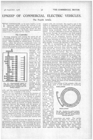
Fig. 19.—Diagrammatic sketch of controller, open, showing the cylinder with the sector contacts and the spring contacts.
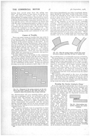
magnet coils, are reversed ; the negative end of the battery is connected to that end of the field magnet coils, or to that brush to which the positive was connected when running ahead; the positive end of the battery being connected, where the negative was before. It is not sufficient to reverse the direction of the current through the armature and field magnet coils as a whole ; that will not reverse the direction of rotation ef the armature, because though the current is reversed, it still flows through all the coils in the same direction as before ; reversing its direction through one of them, either the armature or the field magnet, reverses the direction of the motion. • All this is accomplished by the controller, by merely moving the lever which operates it forward when starting, backward when reducing speed, and back beyond the neutral point when reversing; or moving the wheel round in one direction or the other when the controller is vertical. Fig. 19 is a diagrammatic sketch of a typical controller, open • it consists of a hollow cylinder of an insulating substance, carrying sectors of brass or copper on its surface, the sectors being of different lengths in arc. The different sectors are connected to different points in the circuit by means of insulated wires carried inside the cylinder of insulated material. The sectors are faced by contacts carried by springs that are held by, but insulated from, the oontaining ease; the springs and their contacts are connected to different points in the circuit by means of insulated wires. By revolving the cylinder of insulating material, different sectors are brought into contact with different springs, and different connections are made, just as they would be by a number of separate switches. *The controller is, in fact, a Mutiple switch ; it is a number of switches, four, six, eight, or more separate switches contained in the one case, the lever, or the wheel, which moves the cylinder taking the place of the insulated handle of the separate switches. Fig. 20 is a cross section of the cylinder with one sector fixed upon it and embedded in insulating material, showing the contact and the instilated spring, t h e contact bearing against t h e sector. When the cylinder revolves, th at contact is moved away from the conducting sector on to the insulating material,and that particular Fig. 20.—Seciion of a sector contact, circuit. being on the insulating cylinder, embedded broken.' Fig_ 21 in insulation, with the spring contact shows diagrambearing against it.
matically how the different connections are made. The ,spring contacts are shown one below the other on the left, whilst the sector contacts are expanded, in the different positions they take up, on the right. As the insulated cylinder moves round, the different sector contacts bear against the spring contacts opposite to them, the other sector contacts
INSULATION
having been moved away from the spring contacts. As each sector in turn leaves its spring contact, 'that circuit is broken, and, as each in. turn bears against its spring contact, that circuit is closed. Usually, the first contact made when the starting lever is thrown forward makes connection between the battery and the motor, with all resistance in circuit and with the other arrangements made to reduce the pressure. As the lever moves forward, the first. contact is broken and the second made ; this meaning that a partof the resistance is cut out, and so on. The action is exactly the same when starting, as v. ith the ordinary starting switch and resistance of any electric motor.
Causes of Trouble.
There are many causes of trouble that may arise in the controller ; one very likely (and very serious) cause is the disconnection of connecting wires at either the brackets of the contact springs, or the sector. If one of these should become disconnected, that switch is put out of action and the circuit between the battery and the motor may be broken, with the result that no current flows through the motor coils. All connections inside the controller should be very carefully examined periodically. Wires are very apt to break where they are connected to terminals, and particularlY when exposed to vibration. Another likely source of trouble is the connection between the spring contacts and the sector contacts. The spring contacts should always bed on the sectors as shown in Fig. 22, not as shown in Fig. 23. There is the same danger at' these contacts as with the brushes on the commutator of the motor. If they are allowed to wear, so as only to present a knife edge to the see tor, disconnection will very probably follow, and in any case a resistance will be set uplaetween the two contacts that will prevent the controller doing its work properly. The circuits, where the contacts are in this condition, will have a higher resistance than where theg contacts bed properly, and the currents _flowing through them will be at lower strength than they should be, leading to lower starting torque, lower running torque, etc.
The contacts naturally wear in proportion to their use, partly due to .friction between the two metals, but more to the spark that passes when the circuit is opened. All controller contacts should he 'carefully examined periodically and care should be taken that the spring contacts always bed nicely, both on the sector contact and on the insulating material. The spring contacts should be renewable and it should be practicable to keep them smooth by the aid of sandpaper. Emery paper should never be used upon electric contacts, and sand paper only very carefully. If contacts are watched and both sector and spring contacts are kept true by the aid of sand paper, rubbing B36 them down immediately any little irregularity shows, there should be very little trouble from this source. If they are allowed to wear, and if attention is not giveh to. them before the wear has time to progress, trouble will he sure to ensue.
Another point that is of great importance is the wear of the bearings of the axle of the controller cylinder. Theaxle usually runs in ball bearings, as it is of the greatest importance that there shall be no friction. It is equally important to see that there is no wear upon either the spindle or the balls. Ball bearings have been greatly improved during the last ten years and one can be fairly sure of obtaining good balls and accessories if one pays a fair price. There are tales, however, of badly-made ball bearings giving trouble ; one or two of the balls have worn flat, and the result has been a considerable increase of friction.
The great danger in connection with the bearings of the controller is this: If either the axle, or the bearings should become appreciably worn, there is a possibility of the cylinder running out of truth, and'then imperfect connection will be made between some of the sectors and some of the spring contacts. Wherever this takes place, or 'wherever there is imperfect connection, the electrical .resistance of that particular circuit is increased, the current flowing in it is decreased and the work obtained from the motor is diminished., The 'remarks with regard to the wear of bearings apply with greater force to the bearings of the motor itself. If these wear, the armature is thrown out of truth and useless currents will flow through the armature coils in consequence, leading again to a decrease in the work the motor can perform.
Keeping the Sector Contacts Clean.
It is very important indeed that dust should not be allowed to build up between the sector contacts, nor between the brackets holding thei springs. The fine particles that are worn off the contacts due to their rubbing over each other, and to the, sparks when the circuits are opened, may be deposited between the sectors, and between the brackets holding the springs Any de posit of moisture or oil will assist the deposit of dust and either will form a bed for the dust, which will gradually build up a connection between two sectors, or two brackets, and cut out, or partially cut out, the resistance coils, or whatever may be connected to the two contacts that are bridged over. There is considerable danger oi the deposit of moisture, if the controller has become hot and, later, has cooled down when the ear was in the garage. Warm air often carries a comparatively large quantity of moisture, which it deposits on any surface that may be handy, particularly a cold surface, when the temperature of the air itself is lowered. The remedy is, as in the other eases that have been mentioned, frequent examination, and scareful cleaning of all surfaces where dust can accumulate. Fig. 24.—Dust making connection between two sector contacts.