


Patents Completed.
Page 32
If you've noticed an error in this article please click here to report it so we can fix it.
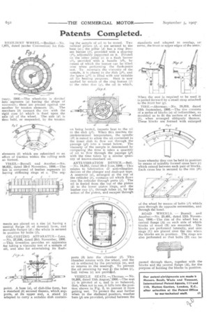
R EST T.TF.NT WHEEL. —Brolliet.—No. 1,871, dated (under Convention) 1st Feb.
ruary, 1906.—The wheel-rim is divided into segments (a) having the shape of vonssoirs ; these are pressed against one another by tension elements (b). The members (b) connect the rim with the rigid core (e) which is fixed upon the axle (d) of the wheel. The axle (a) is thus held, or suspended, by the tension elements (b) which are submitted to an effort of traction within the rolling arch so formed.
T1RES.—Burrell and Another.—No. 26,621, dated 23rd November, 1906.—The tire is composed of leather segments (c) having stiffening rings at e. The seg ments are placed on a rim (a) having a central flange (b) of dovetail form, and movable flanges (d); the whole is secured in position by bolts (f).
OIL-TESTING APPARATUS.—Lees. —No. 27,036, dated 28th November, 1906_ —This invention provides an apparatus for taking a viscosity test of a sample of oil, and also for ascertaining its flash
point. A base (a), of dish-like form, has a standard (6) secured thereto, which supports, at its upper end, a stand (c) adapted to carry a suitable dish contain ing the sample of oil to be tested. Two vertical pillars (d, e) are secured to the base (a); the pillar (d) has a ring Bunsen burner (f), provided with a stop-tap If!), adjustably supported on it. Pivoted on the other pillar (e) is a flash burlier Iel), provided with a handle (e2), by means of which the burner can be tilted over when performing the flash-point test. To ascertain the viscosity of the sample, it is placed in the dish (gl), and the space (0) is filled with any suitable oil for heating purposes. Heat is now applied by means of the ring burner (f) to the outer disc (g), the oil in which, on being heated, imparts heat to the oil in the dish (gl). When this reaches the predetermined temperature, the spindle th2) is raised to allow the oil contained in the inner dish to flow out through the passage (g5) into a vessel below. The viscosity of the sample is determined by comparing the time it takes a quantity of oil to flow through the passage (g5) with the time taken by a similar quantity of known-standard oil.
ANTI-VIBRATION DEVICE.—Bell. .—No. 14,382, dated 23rd June, 1906.—This relates to lubrication of anti-vibration devices of the plunger and dash-pot type. A reservoir (a), arranged at the top of the cylinder (b), contains oil which flows into the cylinder through ports (j). The oil is forced from the top of the piston (d) to the lower piston rings, and the leather cup (f), through tubes (c), by the action of the piston, and escapes through ports (k) into the chamber (I). This chamber rotates with the wheel, and the oil is collected by the pro iection (a), and so returns to the reserv. To prevent the oil returning by way, the tubes (c), ball valves (e) are provi ed.
VEHICLE SEATS. —Thomas.— No. 18,308, dated 15th August, 1906.—The seat
(e) is pivoted at e, and is so balanced, that, when not in use, it falls into the position shown in Fig. 2, to prevent it from getting wet. To protect the seat further when in the sheltered position, weather bars (p) are provided, pivoted between the standards and adapted to overlap, or, cover, the front or upper edges of the seats_ When the seat is required to be used it . is pulled forward by a small strap attached to the front bar (g).
TIRE.—Akerrnan.—No. 20,319, dated 12th September, 1906.—The tire consist& of a series of blocks (a) of indiarubber, so moulded as to fit the surface of a wheel (b), when arranged obliquely thereon. These blocks are formed with enlarged bases whereby they can be held in positiorn by means of suitably formed cross bars (e) which extend between each pair of blocks_ Each cross bar is secured to the rim of the wheel by means of bolts (c1) which]. pass through its opposite extremities, and through the band.
ROAD WHEELS. — Burrell and Another.—No. 25,491, dated 12th November, 1906.—The rim of the wheel has a. central flange (A) on each side of which blocks of wood (B) are mounted. Theblocks are perforated laterally, and side rings (C) are placed over the rim when_ the blocks are in position. The rings are also perforated so that bolts (D) can be
passed through them, together with the. blocks and the central flange (A), for thepurpose of holding the blocks in position.