


A Non-slip Differential Gear
Page 80
If you've noticed an error in this article please click here to report it so we can fix it.
riA DIFFERENTIAL gear that will allow moderate relative turning between the two axles but which will not permit total slipping of one wheel,
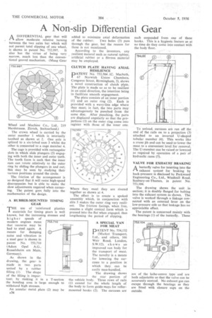
is shown in patent No. 752,997. It also has the virtue of being very narrow, much less than the conventional geared mechanism. (Maag Gear Wheel and Machine Co., Ltd., 219 Hardstrasse, Zurich, Switzerland.) The crown wheel is carried by the outer member 1 which is internally toothed as shown at 2. One axle is splined to a six-lobed cam 3 whilst the other is connected to a cage member 4.
The cage is provided with rectangular slots in which slide plungers (5) engaging with both the inner and outer teeth. The tooth form is such that the inner cam can rotate relatively to the outer ring by sliding the plungers in and out; this may be seen by studying their various positions around the circle.
The friction of the arrangement is so designed that it will resist high-speed discrepancies but is able to make the slow adjustments required when cornering. The patent goes fully into the mathematics of the design.
A RUBBER-MOUNTED TIMING GEAR
THE use of 'reinforced plastics
materials for timing gears is well known, but the increasing stresses and higher speeds of modern engines mean that recourse may be had to steel again. A means for damping noise and vibration in a steel gear is shown in patent No. 753,710 (Adam Opel A.G., Russelsheim am Main, Germany).
As shown in the drawing, the gear is made in two parts united by a rubber filling (I). The shape of the filling is important; by making it in a T-section the bonding area is large enough to withstand high stresses.
An annular metal plate (2) may be A34 added to minimize axial deformation of the rubber. Two holes (3) pass through the gear, but the reason for these is not mentioned.
According to the inventors, any resilient materal such as natural rubber, artificial rubber or a fibrous material may be employed.
CLUTCH PLATE HAVING AXIAL
•• RESILIENCE PATENT No. 752,564. (C. Macbeth, 67 Norwich Union Chambers, Congreve Street, Birmingham, 3), shows a novel construction of clutch plate. The plate is made so as to be resilient in an axial direction, the intention being to facilitate smooth engagement.
The plate consists of an inner portion
(1) and an outer ring (2). Each is provided with a wavy-line edge where they meet; in fact, the two parts may advantageously be punched from the same disc. After punching, the parts are displaced angularly so that the projections (3) on the outer ring come into register with those of the inner one.
Where they meet they are riveted together as shown at 4.
The effect is to create a spoked assembly which, in conjunction with slits 5 makes the outer ring very resilient. The friction facings, when free, assume. a slight conical form which is pressed into the flat when engaged, thus lengthening the period of slipping.
A SPECIAL VAN FOR MEAT
PATENT No. 754,132 (Market Transport, I,td., and others, 166 Weir Road, London, S.W.12), shows an improved van body for the transport of meat. The novelty is a means for lowering the carcases to a position in which they can be easily man-handled.
The drawing shows the rear portion of the vehicle body. Three rows of rails (I) extend for the whole length of the body to form guide-ways for rollermounted hooks (2). The carcases are each suspended from one of these hooks. This is a hygienic feature as at no time do they come into contact with the body floor.
To unload, carcases are run off the end of the rails on to a projection (3) attached to an inverted U-shaped tubular member (4). This works like a crane jib and can be used tolower the meat to a convenient level for removal. The U-member can be raised or lowered as required by operation of a pair of hydraulic rams (5).
VALVE FOR EXHAUST BRAKING
Abutterfly valve for inSerting into the exhaust system for braking by back-pressure is disclosed by Parkwood Engineering Co., Ltd., Windmill Road, Sunbury-on-Thames, in patent No. 753,104.
The drawing shows the unit in section; it is doubly flanged for bolting into the exhaust system as shown. The valve is worked through a linkage connected with an external lever on the low-pressure side so that leakage has no appreciable effect.
The patent is concerned mainly with the bearings (1) of the butterfly. These are of the lathe-centre type and are both adjustable so that the valve can be accurately centred. No exhaust gas can escape through the bearings as they are fitted with closure caps on the outside.