


An Oil Film and Friction Tester
Page 47
If you've noticed an error in this article please click here to report it so we can fix it.
British Timken Device from which Valuable and Precise Data on Lubricants and Bearing Metals Can Be Obtained
ACCURATE information on the load-carrying ca of lubricants, on friction and the wear-resistin perties of materials can be obtained by means of a machine recently introduced by British Timken, Ltd., Cheston Road, Aston, Birmingham. It should prove of value to users and producers of oils, machinery of all kinds, bearings and bearing metals. It supplies data which is usually regarded as obtainable only from the laboratory:
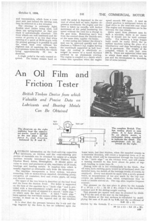
The machine incorporates a lever system, test-piece mounting, belt or motor-driven mandrel, circulating pump, one-gallon oil container, feed and return pipes, oil sump and electric heater.
The upper of the two levers is described as the load lever and the lower the friction lever. The latter is supported on the base of the machine by a 'knife edge" and provided with a fine-adjustment weight and •a stop. minediately above its point of support is a second "knife dge " on which rests the load lever. A third "knife dge " bears against the test-block carrier, whilst the test cy inder, ()Biotin, is fixed on to the tapered end of the in chine mandrel.
It is clear that the pressure between the teock a d the cup, imposed by the force A, has no influence upon the
acities g prosimple
lower lever, but that friction, when the mandrel rotates in a clockwise direction, will create a tangential force at F on the block, which will be• transmitted through the load lever to the " knife edge" on the friction lever, and will create a turning moment in this lever about its point of support, tending to resist force B.
During tests oil is fed continuously to the block. For oil tests, both rubbing parts would be of hardened steel ; for material tests, toe metals of the bearings would, of course, be employed. Every test should be made with a newly ground block, as measurement of the scar made by the cup constitutes an indication from which comparisons may be made cc results arrived at. The cup, also, requires frequent renewal.
The pressure on the test piece is given by the formula P = 10 (A + C) — 2f (B + R), where C is the load-lever constant and R the sliding-weight reading.
Test pressure per square inch may be obtained by dividing P by the area of the scar on the test-piece: The friction at the test surfaces is calculated by multiplying the sum of B and R by 9.45, and the co-efficient of 9.45 (B R) friction by the formula U — 10 (A + C) —2.5 (13 + R).