


Patents Completed.
Page 24
If you've noticed an error in this article please click here to report it so we can fix it.
A Magnetic Friction Clutch. Tubular Wheel Construction. An Electric Engine.•starter. A Heavy-fuel Carburetter.
Copies of complete specifications of the patents published on this page can be obtained from the Sales Branch, Patent Office, Holborn, W.C., at the cos' of sixpence for each specification.
MALCOLM WALKER AND SMITH AND COVENTBY.—No. 11,409, 1915, dated 7th February, 1916.—A magnetic clutch. may be single, or double to give a reverse motion as shown in the example of the invention iliukrated. When current is off, the central driving block is held by a brake, and, being keyed to the shaft, the shaft remains stationary, the clutches revolving freely on the sliaSt and in opposite directions.
Each clutch consists of three members. The Magnetic member is the outer part running on ball-bearings and carrying the electric energizing coils in an annular reoess of its inne? face. Against the coils, or polar face, is the armature of flat ring shape and carried on studs which allow lateral movement. Between these two is the friction member with cone-shaped friction surface making contact with a corresponding internal surface in the magnet. On current being switched to either clutch, the magnet and armature press tawards each other, forcing the friction cone into action. Springs may be used on the cross-pins to keep the magnetic and armature members apart when de-energized. In other examples of the invention a friction surface is also shown on the armature so that the driving cone is gripped on both sides.
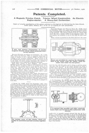
J. BLAKE, No. 13,037, dated 11th September, 1915.—This invention provides an improved construction of road wheels for motor vehicles of the type in which the nave and rim are connected by tubular spokes. The nave and rim are each formed with sockets within which is situated a bridge piece, and the tubular spoke has two opposite lugs on the ends which enter the socket and are bent down across the bridge piece. Preferably the parts are shrunk together when assembling them, and they may be further strengthened by welding if desired. This construction is applicable to single or twin wheels with any arrangement of spokes. B017LTLEE BROOKS AND WILLIAM HOLT, No. 17,008, dated 3rd December, 1915.—An engine starter of the electric-motor type is-normally held out of action by spiral springa as shown in the drawing. The driving pinion is cut on a small shaft which fits into a tubular hollow, in the armature shaft,. In this position the armature is out of line with the field windings.
When current is switched on the field coils force the arms
ture into line with the poles, and in doing so pull the pinion into gear with the teeth on the engine flywheel (of which a portion only is shown). As the engine develops speed under its own power the flywheel tends to drive the pinion and the armature, ,Zvith the result that the current in the field weakens and the compressed springs are free to extend and the starting motor is automatically disengaged..
The screw on the pinion-shaft assists to complete engagement or disengagement of the gear. The details include a stop at one end of the pinion-shaft and a cushion at the other to limit the lateral movement of the pinion in either direction.
S. R. Townsmm, No. 100,929, dated 27th May, 1916.—In this carburetter the fuel is supplied to a horizontal jet-tube which is. controlled by a needle-valve, and the throttle valve. is constituted by two pivoted flaps which are geared together to move in unison and open or close the induction pipe. The needle-valve is normally pressed forward into the jet by a spring; a cam-surface is provided on one of the throttle flaps to withdraw the needle valve automatically as the throttle is opened. One of the throttle flaps carries a flexible plate, which lies against the other flap wheD in the closing position and is formed with a IT:notch to provffle for the gradual opening of the throttle.