


Automobile Fire-engines.
Page 13
Page 14
Page 15
If you've noticed an error in this article please click here to report it so we can fix it.
A Description a the Pumps Employed on the Principal German Engines, Compared with the Gwynne, as Fitted to a Dennis.
By an Engineer Contributor.
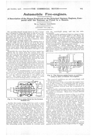
( Concluded from page 59., The specially-shaped trough shown in Fig. 3 (page 59) is designed to cause the water to fall in two cascades into the introductory channel (L). It should be noted that the latter is divided into three compartments by `means of two ribs (FE). The water. falls principally into the• two outer chambers, while the central one contains mainly air. At this stage the slide valve to the suction hose is opened a little and air is drawn out of it, the water making the pump act as an air evacuator, and the. mixture of air and water is passed through the pump to the water tank, where the air separates from the water and escapes to the atmosphere through a vent pipe.
Meanwhile the water from the low-level supply has replaced the air taken from the suction hose, the slide valve for the latter has been completely opened, and the condition for normal operation has been established. The conduit from the water tank to the suction chamber is now first closed, whereby the tank is refilled, when both conduits are closed.
. Trials with this pump have shown that water can be raised 29 ft. in one minute without failure, and that in subsequent normal operation the pump continues to raise water this height, while at the same time developing a pressure of eight atmospheres, corresponding to the work of raising the water inside the hose to a height of 260 ft.
With four hoses simultaneously at work, each with an interior hose diameter of 2 ins, and a nozzle diameter of in., streams were thrown to a height of 72 ft., and the •delivery amounted to 210 gallons per minute. The engine in the Adler machine to which this pump is fitted develops 40 h.p. at 1500 r.p.m.
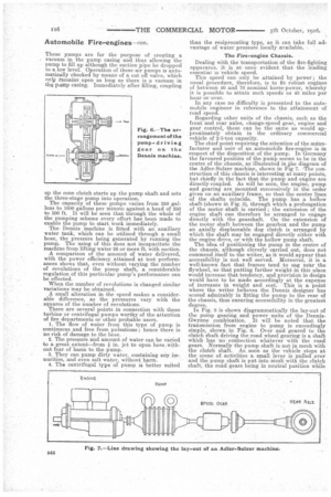
Another fire-engine pump which has made a name for itself all aver the Continent is the Sulzer, which is the standard fitment to the German-Daimler machine. This pump, which is shown in section in Fig. 4, is of the three-stage centrifugal type. The pump casing is provided with a jacket forming a chamber for the cooling water of the motor, and the pump connection nozzles are at the same time utilized for fixing the pump on the chassis. There are two suction inlets 4 ins, inside diameter and two delivery outlets 2g ins, inside diameter. The exhausting pump is driven by the main pump shaft, and is combined structurally with the casing of the centrifugal pump. Moreover, this pump is so constructed that water can be pumped without risk, as well as air., and, therefore, the exhausting pump can remain in constant gear
with the centrifugal pump, and can run uninterruptedly. It will be readily understood that in a pump of this type the speed of the pump shaft is the factor by which efficiency is secured. This speed, it might be said, takes the place of the close fit of the piston and the alternating closing and opening of the valves in positive pumps. The maximum pressure that can be attained in the pipes and hose of a centrifugal pump is that determined by the pump-shaft speed. Consequently, to obtain efficiency without the medium of gearing, it is necessary that the automobile motors used in fire engines of this type should be high-speed engines, giving their best torque at over 2000 r.p.m.
The required conditions arc met exceedingly well in the Dennis machine.
As the pioneers of the automobile fire-engine business in this country, it is apparent that the success of Dennis Bros. (1913), Ltd., Guildford, lies in producing a machine evolved from the co-operation of specialists. This is readily understood when it is seen that the power plant consists of a White and Poppe engine and the pump is a Gwynne. These form a most efficient combination.
A diagram of the pump is shown in Fig. 5; it will be seen that it is of the three-stage centrifugal type, in which the rotors take the water in the centre and deliver it to the outer cases through a cone-type nozzle.
At 1000 r.p.m. this pump is capable of extremely high pressure varying only by the amount of water delivered to it through the suction pipe. When a normal jet is required, hose pipes can be connected to the pump casing through apertures in the centre'.
The delivery pipes for two hoses are on the extreme right hand of the pump, and are controlled by wheel valves. In connection with these valves there is a fitment which enables the machine to start rapidly. Each delivery pipe has a flap valve, which remains closed whenever there is a vacuum in the pump casing, and opens when there is pressure in the dtlivery pipe. Consequently, it is not necessary to close the valves with the hand wheels, and the hoses are connected direct to the delivery pipes, and require no further attention on the part of the operator. On the end of the pump shaft is a small cone clutch geared to the shafts of two reeiprocating air pumps.
• 1143 These pumps are for the purpose of creating a
, vacuum in the pump casing and thus allowing the pump to fill up although the suction pipe be dropped to a.low level. Operation of these air pumps is automaticay checked by means of a cut off valve, which nnlit temains open as long as there is a vacuum in the pump casing. Immediately after filling, coupling
up the cone clutch starts up the pump shaft and sets the three-stage pump into operation. The capacity of these pumps varies from 350 gallons to 1000 gallons per minute against a head of 250 to 300 ft. It will be seen that through the whole of the pumping scheme every effort has been made to enable the pump to start work immediately. The Dennis machine is fitted with an auxiliary water tank, which can be utilized through a. small hose, the pressure being generated by running the pump. The using of this does not incapacitate the machine from lifting water 26 or more ft. with suction. A comparison of the amount of water delivered, with the power efficiency attained at test performances shows that, even without varying the number of revolutions of the pump shaft, a considerable regulation of this particular pump's performance can be effected.
When the number of revolutions is changed similar variations may be obtained. A small alteration in the speed makes a considerable difference, as the pressures vary with the squares of the number of revolutions.
There are several points in connection with these turbine or centrifugal pumps worthy of the attention of fire departments or other probable users. 1. The flow of water from this type of pump is continuous and free from pulsations ; hence there is no risk of damage to the hose. 2. The pressure and amount of water can be varied to a great extent—from * in. jet to open hose without fear of harm to the pump. 3. They can pump dirty water, containing any impurities, and even salt water, without harm.
4. The centrifugal type of pump is better suited than the reciprocating type, as it can take full advantage of water pressure locally available.
The Fire-engine Chassis.
Dealing with the transportation of the fire-fighting apparatus, it is at once evident that the leading essential is vehicle speed. This speed can only be attained by power ; the usual procedure, therefore, is to tit robust engines of between 40 and 70 nominal horse-power, whereby it is possible to attain such speeds as 40 miles per hour or over.
In any case no difficulty is presented to the automobile engineer in reference to the atiainment of road speed. Regarding other units of the chassis, such as the front and rear axles, change-speed gear, engine and gear control, these can be the same as would approximately obtain in the ordinary commercial vehicle of 2-3-ton capacity.
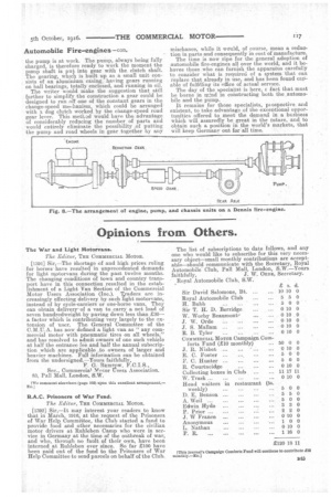
The chief point requiring the attention of the menufacturer and user of an automobile fire-engine is in respect of the disposition of the pump. In Germany the favoured position of the pump seems to be in the centre of the chassis, as illustrated in.the diagram of the Adler-Sulzer machine, i shown in Fig 7. -The construction of this chassis is interesting at many points, but chiefly in the fact that the pump and engine are directly-coupled. As will be seen, the engine, pump and gearing are mounted successively in the order given on an auxiliary frame, so that the centre lines of the shafts coincide. The pump has a hollow shaft (shown in Fig. 3), through which a prolongation of the motor shaft is carried ; the extension of the engine shaft can therefore be arranged to engage directly with the gearshaft. On the extension of the motor shaft between the gearbox and the pump an axially displaceable dog clutch is arranged by which the shaft may be engaged directly either with the engine drive, or with the hollow pump shaft.
The idea of positioning the pump in the centre of the chassis, although cleverly carried out, does not commend itself to the writer, as it would appear that accessibility is not well served. Moreover, it is a well-known fact that frames tend to sag near the flywheel, so that putting further weight in this place would increase that tendency, and provision in design would have to be made accordingly at the expense of increases in weight and cost. This is a point where the writer believes the Dennis designer has scored admirably in fitting the pump to the rear of the chassis, thus ensuring accessibility in the greatest degree. In Fig. 8 is shown diagrammatically the lay-out of the pump gearing and power units of the DennisGwynne combination. It will be noted that the transmission from engine to pump is exceedingly simple, shown in Fig. 6. Over and geared to the clutch shaft driving the road wheel gearing is a shaft which has no connection whatever with the road gears. Normally the pump shaft is not in mesh with the clutch shaft. As soon as the vehicle stops at the scene of activities a small lever is pulled over and the pump shaft is put into mesh with the clutch shaft, the road gears being in neutral position while
the pump is at work. The pump, always being fully charged, is therefore ready to work the moment the pump shaft is put into gear with the clutch shaft. The gearing, which is built up as .a small unit consists of an aluminium casing, having gears running on ball bearings, totally enclosed, and running in oil. The writer would make the suggestion that still further to simplify the construction a gear could be designed to run off one of the constant gears in the change-speed merthanism, which could be arranged with a dog clutch worked by the change-speed road gear lever. This method would have the advantage of considerably reducing the number of parts and would entirely eliminate the possibility :of putting the pump and road wheels in gear together by ally
mischance, while it would, of course, mean a reduction in parts and consequently in cost of manufacture.
The time is now ripe for the general adoption of automobile fire-engines all over the world, and it behoves those who can furnish the apparatus carefully to consider what is required of a system that can replace that already in use, and has been found capable of fulfilling its office of actual service.
The day. of the specialist is here' fact that must be borne m mind in constructing both the .automobile and the pump. It remains for those specialists, pi ospective and existent, to take advantage of the exceptional opportunities offered to meet the demand in a business which will assuredly be great in the future, and to obtain such a position in the world's markets, that will keep Germam, out for all time.