


Increasing the Flexibility of Torsion Bars
Page 54
If you've noticed an error in this article please click here to report it so we can fix it.
TORSION bars, as used in suspension 1. systems, operate through only a few degrees, which means that thearm carrying the axle must be of considerable length in order to give a reasonable amount of rise and fall. To reduce the length of the arm by increasing the flexibility of the torsion bars is the aim of a scheme shown in patent No. 602,892, by Societe des Constructions M dcaniques Chenard et Walcker, Gennevilliers, France.
The chief feature of the scheme is that, instead of a single rod, a bundle of small rods is used as the resilient member. The drawing shows a halfwidth assembly in which the wheel is mounted on a short arm (1) journalled in a frame bracket (2) which is lined with friction material for damping purposes. The bundle of rods (3) is housed inside a tubular member and extends across the frame, being anchored at its mid-point to a bracket (4).
The most favoured form for the individual rods is that of a square, but if' maximum stresses are expected, a hexagon shape may be preferred.
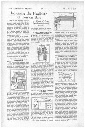
FRONT MOUNTING OF A DYNAMOTOR E once-popular dynamotor seems to be returning to favour for use as a combined starter-motor and generator, possibly on account of the higher voltages now being employed. Such a mach ne is shown in patent No. 602,680, by W Watson, and Mabley and Kallenborn, Ltd., Great South West Road, Hounslow, Middlesex.
When such a unit is attached to the front end of the engine crankshaft, the starting-handle dogs have to. be fitted on the armature spindle, which may, in consequence, • be strained during a, difficult bout of hand starting. To avoid this is the object of the design; in this case the armature shaft is tubular and of large diameter, so that ;the starting dog (1) can be attached directly to the crankshaft. Use is also made of the tubular shaft for cooling purposes, air .beingdrawnin through the front end (2), and passing through. gaps (3) in the shaft, the air stream traverses the 1.1;:lcl. winding (4), and finally makesits exit from under a cowl (5). A centrifugal fan (6) creates the draught, but
a36
the forward motion of the vehicle... is also of assistance in this respect.
A VALVE LAYOUT GIVING INCREASED POWER
PATENT No. 603,634 comes from R. Pescara, Lisbon, Portugal, and describes an improved layout for the valves of an engine. The aim is to provide the largest possible valves in the snace available.
The inlet valve (1) is the larger, and is sloped as shown, whilst the exhatist valve (2) is vertical. • The inlet valve is contained within the cylinder-bore area, but the exhaust is set over to one side in a slight pocket, which also houses the sparking plug (3). Both valves are actuated ,by rockers set at an angle so that they line up with the push rods, all of which are located on one side of the cylinder. block.
The scheme is said to enable highcompression engines 'to be made at less , cost The improved head may be fitted to an existing engine, in which case a considerable increase in power is claimed. The patent also covers some modifications to the arrangement of the inlet and exhaust passages.
SAFETY SWITCH FOR ELECTRIC STARTERS
ONCE an engine is running damage may be done to the starter-pinion if the switch be accidentally operated,
and to prevent this is the objct of a device shown in patent No. 602,399. The patentees are C.A.V., Ltd., and W. Bevis, both of Warple Way, London, W.3.
In this scheme, the driver does not close the actual starter circuit, but only a relay circuit containing an electro
magnetic switch. . In the drawing, 1 is a rocking armature, 2 a magnet winding switchable to the _battery, and 3 a second winding connected to the dynamo. The points (4) form part of the driver's relay circuit.
In operation, when the starter button is pressed, the left-hand magnet is energized, closing the contacts and enabling the main switch to be electrically .closed. But it the dynamo be generating, as it would if the engine were running, the right-hand ' magnet holds the points open, and any subsequent closing of the driver's circuit has no effect.
HEAT INSULATION IN INTERNALCOMBUSTION TURBINES
THE high operating temperatures of gas turbines create many problems in connection with heat insulation, and proposals to deal with this are made in patent No. 602,149. The patentees are the Anglo-Saxon Petroleum Co., Ltd., and I. Lubbock, both of St, Helens Court, London, E.C.3. '
The patent states that in a gas turbine the primary `zone of the combustion chamber may have to operate at 1,400 degrees C, or more, a temperature at which few metals possess any durability, and it is therefore proposed to employ a refractory lining at this point. But such a lining, when used near a high-speed turbine, must be attached in such a manner that there is no possibility of small pieces breaking off and being carried into the Wading, where they would cause great damage.
The drawing shows a part-section of the proposed chamber, which consists of an outer shell divided -into two.coricentric air-cooling jackets (1 and 2) and , an inner shell (3). The latter is fitted with wedge-shaped ribs (4), also internally air-cooled, between which are held refractory blocks (5) made" of zirconia or carborundum. The innermost lining (6) is made of molybdenum • alloy, which, although subject to the high temperature. is not stressed -appreciably, because its only duty is to prevent particles of the refractory lining from falling into the gas stream.. Beftire reaching the' birbine blade's the' gas is cooled to about 800 degrees C. by the admixture of further air