


Centrifugal Clutch with Free Bob-weights
Page 36
If you've noticed an error in this article please click here to report it so we can fix it.
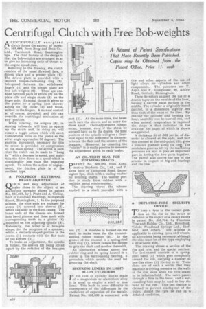
A CENTRIFUGALLY energized clutch forms the subject of patent No. 555,686, from Borg and Beck Co., Ltd., Tachbrook Road, Leamington Spa. The chief feature of the design is that the bob-weights are arranged so,as to give an increasing ratio of thrust as the engine speed rises.
Referring to the drawing, the clutch consists of the usual flywheel face, a driven plate and a presser plate (1)The driven plate is provided with a resilient torque-cushioning ring (2). Interposed between the withdrawal fingers (4) and the presser plate are free bob-weights (6). These are confined between pairs of struts (7) onthe plate side and single struts (5) on the finger side. External thrust is given to the plates by a spring (not shown) acting on the collar (3) and transmitted to the fingers. A manual control
• is, of course, provided, and this can override the centrifugal mechanism at any position. .
When rotating, the weights (6), in moving outwards, will tend to square up the struts and, in doing so, will create a toggle action which will exert considerable force on the plates as the strut angle approaches 90 degreeS. The endwise movement, necessary for this to occur, is provided by compression of the. main spring. The action is such that the clutch can be made to " hang in " with a decrease in speed, and maintain the drive down to a speed which is considerably less than the engaging speed. To soften the action of engagement, the friction plate is of the resilient type.
A FOOLPROOF EXTERNAL BRAKE ADJUSTER
QUICK and easy adjustment of brake shoes is the object of an anchor-pin spreader shown in patent No. 555,661, byj. Pratt and A. Girling, both of Guildhall Buildings, Navigation " Street, Birmingham, 1. In the proposed scheme, the shoe ends are engaged by struts (5) screwed into sleeves (2), which can slide in the fixed casing. The inner ends of the sleeves are formed into bevel pinions and these mesh with corresponding teeth on a pinion (4) „ mounted on the adjusting spindle (3). Externally, the latter is of hexagon shape, for the reception of a spanner, whilst a similarly shaped portion in the centre (1) contacts with the flat ends of the sleeves (2).
To 'make an adjustment, the spindle is turned, the sleeves (2) being forced apart by the rotation of the hexagon
part (1). At the same time, the bevel teeth turn the sleeves and so screw the shoes apart. Over-adjustment cannot occur, because, even' if the shoes be screwed hard on to the drums, the final position of the spindle will give a clearance equal to the difference in diameter between the flats and the corners of the hexagon. Moreover, by counting the "
clicks" it is easily possible to measure the adjustment given to each brake.
AN OIL-TIGHT SEAL FOR ROTATING SHAFTS
PATENT No. 555,385, from Automotive Products Co., Ltd., and F. Eves, both of Tachbrook Road, Leamington Spa, deals with a sealing washer for rotating shafts. The washer portion is made from rubber with , a resilient metal reinforcement.
The drawing shows the scheme applied to . a shaft provided With a nut (2). A shoulder is formed on the shaft to make room for the channelsection rubber washer (3). In the groove of the channel is a spring-steel split ring (1), which causes the rubber to grip the shaft and revolve therewith,
An alternative scheme shows the rubber ring and its spring housed in a• recess in the ,surrounding bearing, a procedure which avoids the need for grooving the shaft.
SECURING LINERS IN LIGHT. ALLOY CYLINDERS
IN the case of cylinder blocks made of a magnesium or aluminium alloy it is usual to employ a steel or iron line. This leads to some difficulty in consequence of the differences in the coefficient of expansion of the metals. Patent No. 555,639 is concerned with
thisand other aspects of the use of light alloys for cylinders and other components. The patentees are F.
• Aspin and F. Ellinghouse, 39, Ashley. Road, Solihull, Birmingham.
These inventors suggest the use of a double taper on the outside of the liner, leaving a narrow waist portion in the middle. The cylinder is originally bored parallel, to a dimension slightly less than that of the waist of the liner. By heating the cylinder and freezing the liner, assernbly can be carried out, and when normal temperature is regained the shape is that indicated in the drawing, the taper of which is shown exaggerated.
A shrinkage fit of .002 per in. of 'diameter is allowed at the ends, and half this amount at the mid-point; this gives a pressure gradient along the linu. The miniature grooves left by the maehining processes are said to play an important part in keying the two parts together. The patent also covers the use of the scheme in respect of big-end bearings and the like.
TO keep a tyre in the correct position on the rim in the event of deflation is the object of a device shown in patent No. 555,754, by Firestone Tyre and Rubber Co., Ltd., Brentford, Toledo Woodhead Springs Ltd., Sheffield, and others. The scheme is applicable to existing tyres and wheels, no alterations being necessary, although the rims must be of the type employing a detachable side.
The drawing shows a section of the rim and tyre, and the special retainer. The last-named consists of a springsteel band (2) which goes completely around the rim, carrying a number of box-like shoes (1) riveted to it. These shoes are of such a width that they .maintain a driving pressure on the walls .of the rim, even when the tyre ceases to be inflation-held. The valve passes through a hole in the band, and a surrounding boss maybe used to key the band to the rim-. This last feature is claimed to prevent tearing-out of the valve, should the tyre be • run in a deflated condition.