


Leyland Offers 16 New Underfloor engined Chassis
Page 40
Page 41
If you've noticed an error in this article please click here to report it so we can fix it.
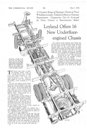
1 "I HE Royal Tiger range of underfloor-engined chassis, made by Leyland Motors, Ltd„ Leyland, Lancs. and briefly described in The Commercial Motor" last week, comprises 16 different chassis. There are eight models of 15-ft. 7-in, wheelbase, all having a front overhang of 6 ft. 5 ins The four bus chassis of this wheelbase have a rear overhang of '7 ft. 7 ins., whilst that of the coaches is shortened to 3 ft. 2i ins. In the coach chassis, the spare wheelis carried forward of the front axle and can be lowered from position withOut effort by means of -a built-in Winch. These chassis are of 7-ft. 6-in. and 8-ft. width.
In addition, there are four chassis of 17,f t. 6-in, wheelbase and four of 20-ft. 4-in, wheelbase for_ Overseas operation. All are 8 ft.. wide. They have a front overhang' of 6 ft -5 ins, and the rear of the frame extends 8 Tt. 3 ins, beyond the axle on the bus chassis and 3 ft. 2 ins: on the coaches. Four of the Overseas models are available with left-hand control.
The short-wheelbase models are designed for a body length of 30 ft., whilst the 17-ft. 6-in. and 20-ft. 4-in, wheelbase chassis are constructed for bodies of 33 ft. and 35 ft. 6 ins. respectively.
Except for a slight sweep over the rear axle, the frame assembly is level and fitted with outrigger brackets So that the body can be built directly on the frame without need for packing. When the chassis is equipped with 10.00 by 20-in. low-pressure. tyres, and is fitted with a body and equipment, the top of the frame at the rear is 3 ft. .,2i ins, above ground level. It is 3 ft. 1 i ins. above ground at the front axle.
c4
The position of the batteries, spare wheel, fuel tank and air Or vacuum reservoir can be varied on the bus chassis to suit a front, centre or rearentrance body.. In the coach chassis, the spare wheel is carried below the frame next to the driving position, and because of the Short rear overhang. the brake vacuum reservoir is mounted inside the frame alongside the propeller shaft and the ,batteries are carried, transversely behind.the rear axle. 'The fuel tank is secured from the outrigger brackets.. in front of the rear wheels.
Engine, clutch and gearbox form an integral unit, which is flexibly suspended amidships on the fram!. at the rear, on links fitted with Elarrisflex 'bushes and supported at the front on a rubber bonded bush which constrains theunit to oscillate on an axis between the centre of gravity and front propellershaft joint. The engine, clutch and gearbox are offset by 3i ins, from the centre line of the frame to bring the exhaust branch clear of the side member.
The mounting of the engine, clutch and gearbox is arranged so that the whole unit can be removed, replaced and started up in less than 50 minutes: Many of the engineer's tasks are lightened by the careful placing of the horizontal engine and its components. Units such as the heads can be exchanged in position in two hours. The fuel pump can be removed, replaced and timed in 11 minutes, and a water-pump change can be made in 15 minutes. An unusual feature is the mounting of the air filter on a boxed-in outrigger bracket which acts as a duct to the induction manifold.
Cooling is effected by a radiator located in front of the engine with a close-eowled fan driven from the front of the crankshaft, As in the Olympic chassisless-construction model, there is no header tank to the cooling system, but where interior heating of the saloon is required, two additional .radiators are fitted inside the frame and connected to the water-circulation system. Thermostatically controlled fans pass air from the exterior of the vehicle through these radiators into ducts and along the length of the body below seat level.
Power is transmitted to the spiralbevel axle froth the four-speed inertialock synchromesh gearbox, in Which synchronizing cones determine the relative gear speeds of the top, third and second ratios before engagement. The gear ratios are 5.0, 2.63, 1.59 and 1 to 1 forward, with 6,13 to I reverse.
A representative of "The Commercial Motor drove one of the chassis with vacuum assistance for gear selection. This provides a light gear-change movement which, at the same time, is positive and lessens driving fatigue. Tubular shafts carried in self-aligning bearings and equipped with simple universal joints are used between the gearbox and remote-control selector lever, The rear-axle casing is a frabricated structure with a cast-steel centre and tubular ends bolted in position. Three final-drive ratios are available for all models, the standard being 4.625 to I; the others are 4.111 and 5.143 to 1. The axle shafts are fully floating.
C.D. or Westinghouse
The Clayton Dewandre triple-servo braking system is supplied on four of t h e short s wheelbase models, the exhauster being attached to an extension of the timing case and sharing a gear drive with the 'fuel-injection pump. Overseas models and the remaining four short-wheelbase chassis have Westinghouse air-pressure equipment, and an 11-cubic-ft. two-cylindered compressor replaces the exhauster at the front of the engine. Air fOr the compressor is drawn through the engine oil-bath air cleaner. The total braking area for both systems is 577 sq. ins.
Alternative tyre and wheel equipment is available for all models, the 15-ft. 7-in. wheelbase chassis having tyres of 9.00 b'Y 20-in. or 10.00 by 20-in. section. For the17-ft. 6-in, wheelbase models.
there are three tyres sizes of 10.00 by 20 ins., 11.00 by 20 ins and 11.00 by 22 ins. The 11.00 by 20-in. and 11.00 by 22-in, sizes are available also on the 20-ft. 4-in, wheelbase chassis.
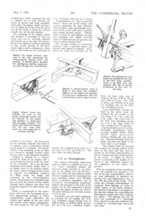
Long semi-elliptic springs are fitted to the entire range, the standard for all models at the rear, being 5 ft. 2 ins, long and 4 ins, wide. The front units of the 15-ft. 7-in, wheelbase chassis are 4 ft. 5 ins, long, whilst all other models have 5-ft. springs.
Spring shackles are of LeylandMetalastik manufacture, incorporating bonded rubber which absorbs rotary movement • between shackle pin and spring eye. Newton telescopic hydraulic shock absorbers are fitted to the front axles of all models.
The chassis frame has parallel side members of channel section which taper at the front and rear, and are braced by 10 bolted cross-members in the bus chassis and nine cross-members in the coach. A length of channel section is inserted at the middle of the frame to give additional support for the suspension of the engine and gearbox.
With the exception of the hand-brake lever, all controls are, secured to the face of the first cross-member, which is set back sufficiently to maintain the steering bent and selector-lever case in line with the front of the frame. Rods which pass through cross-members are protected from damage or rattle by rubber inserts in the frame members. An electrical stop device is arranged on the steering column for controlling the fuel-injection pump rack when stopping the engine. The steering box has its drop arm conneeted to a bell-Crank lever attached to the axle, which in turn is linked by a divided track rod to the stub axles.