


A NEW SUNBEAM
Page 50
Page 51
Page 52
If you've noticed an error in this article please click here to report it so we can fix it.
SIX-WHEELED ri
ZOLLEYBUS
First a High-g] a Hos Weymc Work, 1
Full Particulars of a 3 Chassis, Incorporating )f Interesting Features.
Double deck Body an Enclosed, Straight, )ff-side Staircase
SINCE the, Sunbeam Motor Co., Ltd., of : Wolverhampton—the 'well-known maker of high-grade cars—entered the commercial-vehicle side of the automobile industry, marked interest has been shown by all discriminating operators in the design of both the power-unit and chassis details of the machines in question. We are now able to announce the introduction of an entirely new six-wheeled, double-deck trolley-bus. Through the courtesy of Mr. C. Owen Silvers, A.M.I.E.E., M.Inst.T., general manager and engineer of the transport department of Wolverhampton Corporation, this vehicle will be placed on one of the services in the Wolverhampton district, for a prolonged test.
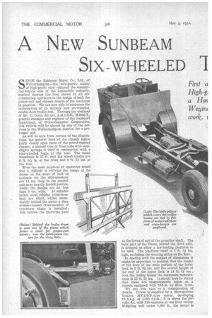
As will be seen from certain of the illustrations, the general lines of the chassis follow fairly closely upon those of the petrol-engined chassis; a normal type of front axle with semielliptic springs is used in conjunction with a four-wheeled bogie at the rear. The mean wheelbase is 17 ft. and the wheel tracks are 6 ft. We in. at the front and 6 ft. 21 ins, at the rear.
Even the most sceptical of operators would find it difficult to criticize the design of the frame on the score of lack of strength for the side-members are 11 ins, deep in the central and most heavily loaded portion, whilst the flanges are no less than 3 ins. wide. At suitable points stout tubular cross-members are fitted, whilst Immediately behind the motor a deep double-channel cross-member of cruciform shape is installed ; this carries the universal joint at the forward end of the propeller shaft. The back part of the frame, behind the third axle, Is dropped to allow a low-loading platform to be used. The platform itself is 1 ft. 51 ins. high, excluding the wearing strips on the floor.
In dealing with the subject of dimensions it might' be opportune to mention that the height of the floor of the main portion of the lower deck is 2 ft. 61 ins, and the overall height of the roof of the upper deck is 14 ft. 71 ins.; over the trolley booms the maximum measurement is 15 ft. 31 ins. It should here be stated that these are measurements taken on a chassis equipped with 10.5-in. by 20-in. tyres.
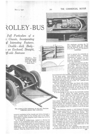
We can now turn to a consideration of details. Power is supplied by a Metropolitan Vickers MV.110.B.-type motor, developing 70 b.h.p. at 1,290 r.p.m.; it is wired for 500 volts d.c. with 118 amperes at one hour rating. Weighing well under 1,000 lb., the motor is mounted amidships in the chassis and drives through a short propeller shaft to the leading axle of the bogie. Thereafter a further propeller shaft takes the drive to the trailing axle.
As is usual in trolley-buses, control is effected by means of an accelerator pedal which actuates a drum switch, provision being made for interlocking the switch with the reverse, neutral and forward switches on the dashboard. To avoid overloading, the control switch itself brings into use contactors which carry the main current ; thus the drum switch merely carries a light load to operate the solenoids on the contactor panel. Suitable resistances are placed on each side of the chassis and are properly ventilated and shielded from the bodywork.
As might be expected, an electric braking gear is included in the layout. This is of the rheostatic type controlled from the left pedal, and is applied through a dram switch moving contactors in the same way as for accelerating. The electric mechanism is Interconnected with Lockheed hydraulic brakes operated by the same pedal. Approximately the first half of the movement of this pedal applies the rheostatic braking, whilst the latter half of the movement holds the rheostatic braking switch on to its " on " position and applies the hydraulic system.
All four wheels of the bogie are fitted with drums, the shoes being hydraulically operated by the service pedal and manually operated for the hand or parking brake. The hydraulic operation of the shoes for the front-wheel brake system is identical with that of the brakes on the live axles.
It is interesting to note that in the hydraulic portion of the system the pedal operates three master cylinders, each of which is connected to one axle ; thus, the front and the two 'rear axles have their separate systems. Compensation for the different volumes of fluid which may exist in each of the three systems is provided for ; should a pipe break, a needle-valve sealing device isolates the disabled system. In this way two axles out of three are always capable of being braked, even in the unusual event of a failure in one of the pipe lines.
For this Sunbeam chassis, a well-designed 61-seater body is being constructed by Weymann's Motor Bodies (1925), Ltd., Station Road, Addlestone, Surrey. The lower saloon has accommodation for 28 seated passengers, and 33 persons can be carried on the upper deck. In the case of the lower saloon there is a full-width seat for five persons at the front, and on each side there are eight double seats. Over the left-hand wheel arch five passengers are carried on a longitudinal seat, and two on a short one over a part of the right-hand wheel arch. Behind and partly over this short seat is the straight staircase with seven treads.
In the upper deck on the right-hand side there are six transverse.doubre Seats, whilst on the left there are nine similar seats and one for three persons at the extreme rear. The rear platform is 61 ft. wide and 4 ft. deep. It permits rapid loading. The tread of the lowest step is hinged to provide a box for the skate which can be thrown out through a trap below.
A feature of the body design is the inward sloping of the sides towards the roof. Below the waist rail of the lower saloon the maximum width is 7 ft. 4 ins., the measurement being 7 ft. 3 ins, at the lower-deck cantrail and 6 ft. 6 ins, at the upper-deck cant-rail. Thus it will be understood that each side slopes inwards to the extent of 5 ins., giving good clearance between the body and a lamp standard when the bus is brought to rest on a steeply cambered road.
In the upper deck there are two half-drop windows of the Quicktho type at the front, the same design of window being employed in the case of the three lights on each side of the bus on each deck. Route indicators are provided at the front • and destination indicators at the sides. These are equipped with handle control operable from below. The upper saloon is made as an entirely separate unit, the joint between the two saloons being covered by an aluminium shroud. In the lower saloon the headroom is 5 ft. 10 ins., and on the upper deck it is 5 ft. 81 ins.
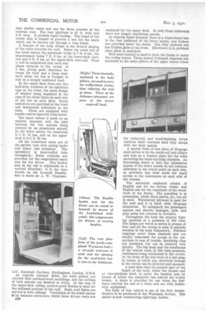
All the transverse seats are of the garden type with spring backs and Alpax cast pedestals. The upholstery is hand-buffed hide throughout ; Sorbo cushions are provided for the longitudinal seats and for the driver. The bucket seat in the cab is adjustable in a vertical direction ; it is the type known as the Leveroll Busella, and is made by A. W. Chapman, Ltd., Ranelagh Gardens, Hurlingham, London, S.W.6.
As regards internal finish, the main pillars are covered with polished-wood mouldings, and the ceilings of both saloons are finished in white. In the case of the upper-deck ceiling, scratch-proof Rexine is used for the radiused portions of the roof. Sunk, oval lights are carried in both ceilings. 'Ventilation of the lower saloon is by Ashanco extractors, whilst three Airvac vents are
B34 employed for the upper deck. In both front bulkheads there are hinged ventilating panels.
As regards detail fitments, there is a waste-ticaet box in the rear bulkhead of the lower saloon, and lockers are provided under the stairs. The fully enclosed cab has Triplex glass at the front. Elsewhere -in. polished plate glass is employed.
Mild steel channel is used to form the frame to carry the trolley booms. Three lateral IT-shaped channels are anchored to the main pillars of the upper saloon below the waist-rail, and wood-finishing strips continue their contours until they merge with the body Panels.
A special form of box plate of 16-gauge steel serves to tie the waist-rail and pillars and acts as a washer plate for the bolts anchoring the boom-carrying channels. An interesting detail is that the aluminium panels of the lower saloon do not continue unbroken to the lowest point on each side, as provision has been made for rapid access to the resistances on each side of the chassis.
The materials employed consist of English oak for the bottom frame and English ash for the remainder of the woodwork of the frame. The panelling is in aluminium, whilst flitch plates, etc., are all in steel. Waterproof plywood is used for the roof and it is lined with 20-gauge aluminium. To safeguard the passengers against any electric leakages, rails and grab poles are covered in Doverite.
Throughout the body the interior lighting operates at a pressure of 500 volts. The lamps are wired in series in groups of four and all the wiring is sunk in suitable recesses in the body framework. Polished cappings cover these channels and are readily removable for access to the connections in case of trouble. Retaining clips are insulated, but can be removed very quickly. The fog lamp and the headlamps of the vehicle work at 250 volts pressure, resistances being interposed in the circuit. At the front of the bus there is a test plug, by means of which any electrical leakage in the circuit can be detected and assessed.
A steel tube runs the greater part of the length of the body, below the chassis and at rear-platform level, to carry the bamboo pole by means of which the conductor can control the trolley booms. A skate is provided for use when the Sunbeam reaches the end of a route laid out with doublewire equipment. The body of this vehicle is one of the first doubledeckers to be produced in the Weymann factory. The maker is now constructing rigid-type bodies.