


An Improved Epicyclic Gearbox
Page 68
If you've noticed an error in this article please click here to report it so we can fix it.
'ROM S. Ashby and Auto Trans' missions, Ltd., both of Upper York Street, Coventry, comes patent No. 702,859, describing an epicyclic gearbox. The scheme shown is actually an improvement on that disclosed in an earlier patent numbered 691,705.
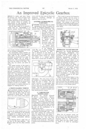
On the input shaft (1) is secured a clutch cone (2). Surrounding it is another conical member (3) forming part of unit 4 which is described briefly as an overdriVe mechanism.
An intermediate clutch member (5) can, by moving right or left, engage the input shaft or the overdrive. The movement is performed by a pair of hydraulic pistons, one of which is shown at 6. This, by pressing on disc 7 can move the clutch to the right. The other, one; not shown, can press on disc 8.
The output member of the clutch is connected to sunwheel (9), whilst the input shaft carries another sunwheel (10). These form part of a conventional epicyclic arrangement in which the planet-carrier is connected to the output shaft (11). Top speed is obtained by coupling the clutch member to the input shaft (leftward movement), second speed by rightward movement and a reverse by braking the annulus (12). The patent does not fully describe the action of the overdrive or how it is coupled. The second speed, it is stated, could also be engaged by braking member 13.
A FRONT-LOADING VEHICLE
AN unorthodox design for a body is disclosed in patent No. 701,864, by E. Preti and M. Salvi, both of Viale Lombardia 8, Milan, Italy. The body shown has a door which, when opened,
uncovers the whole frontal area of the body. If is illustrated in the drawing' as applied to a small car, but it is intended to use the scheme also on fullsized vehicles, particularly delivery vans.
The drawing shows a plan view of the door in the open position. The steering wheel and the other controls move with the door and are fitted with breakaway couplings, although no details of these are given.
AN OTHER RUBBER-SPRUNG SUSPENSION
FURTHER American ideas on rubber springing are shown in patent No. 702,720, by Hickman Industries Incorporated, Eden, New York, U.S.A. The scheme is aimed at providing good suspension at low frequencies such as 85 to 110 cycles per minute. In addition, it is said to permit smaller deflections in all directions other than the main vertical one.
A typical frontwheel layout is shown in the drawing in which &e axle is shown constrained to parallel movement by links I and 2. Mounted on the frame is a pair of brackets to which are bolted metal-faced rubber blocks (3). These are bolted to a central member fitted with a second pair of rubbers at
right-angles. The outer faces of these are bonded to a strap-like plate (4) to which the axle is bolted. The two rubber members at right-angles thus form a type of universal joint which permits controlled movement in all directions. The low operating frequency of the system is claimed to require verylittle shock-absorber control.
A CARBURETTER MODIFICATION
PATENT No. 702,461 (General Motors Corporation, Detroit, Michigan, U.S.A.) shows a detail improvement in the design of carburetters. According to the patent, the fuel passages in a carburetter are liable to create vapour bubbles large enough to obstruct materially the fuel flow, and the aim of the modification is to eliminate this defect.
The drawing shows a carburetter of conventional downdraught type. The fuel, after passing the constant-level valve (1), passes down into space 2, whence it is drawn upwards through a metering plug (3). The fuel then ascends and after turning a corner (4) proceeds to the central jet. The patent is based on the streamlined form of this corner. This is said to prevent the formation of vapour bubbles, and the action is assisted by the provision of a sheetmetal partition (5) in the horizontal passage. The scheme is said to be particularly useful during high-temperature idling, as this is when bubbles are most likely.
HYDRAULIC CLUTCH RELEASE
PATENT No. 702,838 (Brockhouse Engineering (Southport) Ltd., Grossens, Southport) deals with improvements in an earlier design of hydraulic transmission, covered by patent No. 639,675. In this scheme, a hydraulically operated clutch is employed, and the present patent shows a method of hastening its release.
The drawing shows the clutch (1) which is of the multi-plate type. It can be engaged by oil under pressure admitted to the annular space 2. The oil, which is controlled by a governor responsive to both speed and torque, arrives via passage 3. A sliding valve (4) is normally located at the righthand end of its bore.
When the oil pressure begins to rise, it at first escapes via a bleed-hole (5) and then, rising farther, it moves the valve leftwards into the position shown. This uncovers a passage (6) and applies full pressure to the annular piston.
When the oil pressure drops, the valve moves to the right again, cutting off the supply port and uncovering a discharge orifice (7). The oil in the . piston space can thus rapidly escape, in which it is aided by centrifugal force.