


A Crossley Brake-control Layout
Page 68
If you've noticed an error in this article please click here to report it so we can fix it.
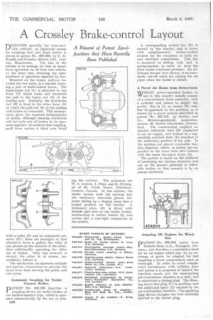
nESIGNED specially for twin-rearLi axle vehicles, an improved means for coupling foot and hand brakes is shown in patent No. 460,058, by F. E. Randle and Crossley Motors, Ltd., Gor ton, Manchester. The aim of the scheme is to arrange for foot or handlever operation on all four rear wheels, at the same time retaining the independence of operation required by law.
Mounted on the frame, midway between the two axles, is a bracket carrying a pair of multi-armed levers. The hand-brake rod (1) is attached to one lever (7) which rocks and transmits the pull to the brake rod (8) of the leading axle. Similarly, the foot-brake rod (6) is fixed to the other lever (3) to which the pull-rod (4) of the trailing axle brakes is connected. This arrangement gives the required independence of action, although running conditions call for both sets of brakes to be operated together. To achieve this coupling, eachlever carries a third arm fitted
with a roller (5) and an adjustable setscrew (2) ; these are arranged so that whichever lever is pulled, the roller of one presses on the setscrew of the other, thus additionally operating the other set of brakes. Only one setscrew is shown ; the other is, of course, immediately behind it.
The mechanism incorporates suitable lost-motion connections to prevent the hand lever from moving the pedal, and vice-versa.
Automatic Coupling for Trailer Vacuum Brakes.
PATENT No. 400,302 describes a coupling device for trailer brakes of the suction-assisted type, which is operated automatically by the act of join
s...10
ing the vehicles. The patentees are W. S. Gurton, J. Flint, and II. Nyberg, all of 00, South Street, Kitchener, Ontario, Canada. In this scheme, the trailer carries both the moving and the stationary turntable plates, the latter sliding up a sloping ramp into a locked position on the -tractor. A stationary plate (2) is fitted with flexible pipe lines to the trailer brakes, terminating in rubber bushes (3), and carries also a roar-light connection in the middle.
A corresponding arched bar (1) is carried by the tractor, and is fitted with complementary rubber-bushed sockets for the reception of both air and electrical connections. This bar is mounted on sliding rods and is spring-backed, in order to keep the joint wider continual pressure. Atiadditional feature (not shown) is an automatic cut-off valve for closing the air pipes when the trailer is absent.
A Novel Air Brake from Switzerland.
ill/HILST power-operated -brakes in VY use in this country usually consist of a conventional drum assembly, with a cylinder and piston to supply the power,. this is by no means the only
• dine of :approach to the problem, as is shown by a novel scheme described in patent No. 400,121, ,I)Sr Oetiker and Co., Motorwagenfabrik, Anemonenstrasse, 40, Zurich-Albisrieden, Switzerland. The construction employs an annular inflatable tube (3) connected to an air supply, and housed in a segmentally notched shell (1) attached to the stationary portion of the axle. In the notches are placed extensible friction elements, which, in action, are expanded by the inner tube into contact with the outer two-piece drum (2).
The patent is based on the methods of anchoring the friction elements, and not on the general principle of inflatable bodies, so that research is by no means restricted.
PATENT No. 459,804 comes from Daimler-Benz A.G., Stuttgart, Germany, and describes a combilstion-head for an oil engine which can, by an exchange of parts, be adaPted forfuel requiring a lower compression,. such as wood-gas. In order to avoid complicated interference with cylinder liner and piston it is proposed to remove the injection nozzle and its surrounding pre-combustion chamber as a Unit, and to substitute a closing Ong. The drawing shows this plug (1) in position, and the additional space (2) vacated by the pro combustion chamber. The sparking plug shown occupies the bore 'normally allotted to the heater plug.