A NEW 6-TONNER FROM FRANCE.
Page 52

Page 53

If you've noticed an error in this article please click here to report it so we can fix it.
A Robustly Constructed Vehicle with a Good Performance, Just Introduced to the British Market.
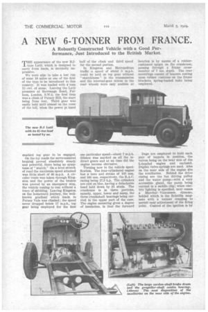
THE appearance of the new E.5.1 type Latil, which is designed to carry 6-ton loads, is decidedly impressive.
We were able to take a test run of some 18 miles on one of the first of the type to be introduced to this country. It was loaded with 4 tons 15 cwt. of stone. Leaving the Latil premises at Stevenage Road, Fulham, London, S.W.6, the first item was a climb of Putney Hill, the start being from rest. Third gear was easily held until almost on the crest of the hill, when the power in hand
enabled top gear to be engaged.
On the icy roads the servo-assisted braking proved absolutely steady and powerful, there being no symptoms of " snatch." On a level stretch of road the maximum speed attained was little short of 40 m.p.h. A circular mute was taken through Kingston and the power of the brakes was proved by an emergency stop, the vehicle coming to rest without a trace of skidding. Leaving Kingston on the homeward journey, the wellknown gradient which leads to Putney Vale was climbed ; the speed never dropped below 17 m.p.h., top gear being employed for the first half of the climb and third speed for the second portion.
In Kingston and Metropolitan traffic a speed of about 5 m.p.h. could be held on top gear without " snatchiness " in the transmission and the internal-gear drives in the rear wheels were only audible at one particular speed—about 7 m.p.h. Silence was marked on all the indirect gears and at no time did the engine become obtrusive.
Turning now to the vehicle specification. The four-cylindered engine has a bore and stroke of 105 ram. and 160 mm. respectively, the R.A.C. rating being 27.3 h.p. The cylinders are cast en bloc, having a detachable head held down by 31 studs. The crankcase is in three portions, namely, upper, lower and sump, the three crankshaft bearings being carried in the upper part of the case. The engine mounting gives a degree of insulation, in that the forward location is by means of a rubbercushioned spigot on the crankcase, passing through a frame crossmember of 7 ins. depth. The rear , mountings consist of bearers resting upon rubber cushions on the frame brackets, spring-loaded bolts being employed.
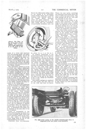
Dogs are employed to hold each pair of tappets in position, the valves beingon the near side of the L-headed engine and enclosed. Duplex valve springs are used. Also on the near side of the engine are the auxiliaries. Behind the drive casing are the fan driving pulley and the water pump—with a very accessible gland, the pump being carried in a saddle clip ; when electric lighting is specified, next comes a Marchal Vaucanson dynamo, behind which is the Scintilla mag
neto with a vernierto permit easy adjustment of the firing point.. Control of the ignition is by
means of a lever and quadrant above the steering wheel. An engine starter can be supplied. On the off side of the engine is the Solex carburetter, equipped with an air cleaner ; fuel is supplied by an Autovac tank on the front of the dash, this drawing petrol from a 25-gallon rectangular tank mounted on the offside chassis member.
The lubrication system is of the force-feed type, using a submerged gear-driven pump which delivers oil to the main bearings, thence through the drilled crankshaft to the connecting-rod bearings and, by ducts, to the camshaft bearings. Other parts are lubricated by splash. A gauge is fitted to the facia board and pressure is regulated by a relief valve situated on the near-side front of the engine, surplus oil being bypassed to the timing case.
Bolted to the end of the crankcase is the pit housing, a dry singIe-plate clutch operated by three finger levers. Immediately behind the pit is the gearbox, which forms a unit With the engine. Four forward speeds and a reverse are provided. The control lever, which works on a ball joint at its base, is carried directly on the gearbox and the knob Is brought within easy reach of the driver's left hand, in whatever gear position it may be. Below the gearbox on the off side is a cover plate which can be removed to disclose an auxiliary drive for operating a tipping gear, or for any other purpose. A mechanical tyre pump can be mounted on the near side of the box if desired.
Power is transmitted to the double-reduction gear by means of a two-piece propeller shaft, which has Spicer universal joints at the front, rear and centre, a ball-bearing steady being fitted in one of the cross-members of the frame.
Suspended from two-cross-mem
bers is the differential casing ; drive to the wheels is by universally jointed shafts which end in pinions meshing with internal gears in the wheels. Spicer universal joints are again employed. The final reduction gears run in an oiltight casing and the crankshaftto-road-wheels revolution ratio can
be either 74 to 1 or 101 to 1.• Of massive proportions is the pressed-steel frame, which has seven cross-members ; one is at the extreme front end, carrying the folding starting handle, one supports the front end of the engine, then there is one behind the gearbox, another carries the propeller-shaft steady bearing, two support the differential, and the last, with large gusset plates, ties together the rear ends of the chassis frame members. In plan, the main channels are straight throughout, the frame width being 2 ft. 11 ins, and the available body space, measured from the back of the dash to the end of the frame,
• is 16 ft. 5 ins., whilst the wheelbase is 13 ft. 7 ins.
Semi-elliptic springs are employed for both axles ; the rear ones are 41 ins, wide and have 14 leaves.
Where the rear spring mountings are attached to the frame, liners are used to stiffen the 'construction. The front springs are 31. ins. wide and are shackled at the front.
The design of the brakes is unusually clean externally, the cams being at the lowest points ; adjustments are effected at the pivots of the shoes instead of in the conventional manner. No tools are required to alter the brake-shoe clearances.
The front brakes operate in conjunction with an internal-expanding brake on the cardan shaft, these being coupled and having a compensating mechanism. They are operated by pedal in conjunction with a Westinghouse servo device. As an indication of the proportions of the , braking mechanism, the cardan-shaft drum dimensions may be quoted: The diameter is 16 ins. and the effective width of face 41 ins. A centrally-situated hand lever operates internal-expanding shoes' in the rear-wheel drums.
Steering is by worm and sector, the • column housing being clamped where it passes through the dashboard. The drop arm is mounted on a spfined sector shaft and the box is carried on a bracket bolted to the frame. Ball-and-socket joints are employed for all steering connections. The turning circle is small for the type of vehicle.
Where pneumatic tyres are specified these are single on the front wheels and twins for the rear wheels, each being 40 ins. by 8 ins. They are carried on steel-disc detachable wheels. If solids be preferred, the tyre dimensions are 1,000 mm. by 140 mm. for the front wheels and 1,030 mm. by 160 mm. for those at the rear.
When the chassis is equipped with pneumatic tyres the price is 025, or with solid tyres £840. It is handled in this country by Latil Industrial Vehicles, Ltd.


