 1
1 2
2 3
3 4
4 5
5 6
6 7
7 8
8 9
9 10
10 11
11 12
12 13
13 14
14 15
15 16
16 17
17 18
18 19
19 20
20 21
21 22
22 23
23 24
24 25
25 26
26 27
27 28
28 29
29 30
30 31
31 32
32 33
33 34
34 35
35 36
36 37
37 38
38 39
39 40
40 41
41 42
42 43
43 44
44 45
45 46
46 47
47 48
48 49
49 50
50 51
51 52
52 53
53 54
54 55
55 56
56 57
57 58
58 59
59 60
60 61
61 62
62 63
63 64
64 65
65 66
66 67
67 68
68 69
69 70
70 71
71 72
72 73
73 74
74 75
75 76
76 77
77 78
78 79
79 80
80 81
81 82
82 83
83 84
84 85
85 86
86 87
87 88
88 89
89 90
90 91
91 92
92 93
93 94
94 95
95 96
96 97
97 98
98 99
99 100
100 101
101 102
102 103
103 104
104 105
105 106
106 107
107 108
108 109
109 110
110 111
111 112
112 113
113 114
114 115
115 116
116 117
117 118
118 119
119 120
120 121
121 122
122 123
123 124
124 125
125 126
126 127
127 128
128 129
129 130
130 131
131 132
132 133
133 134
134 135
135 136
136 137
137 138
138 139
139 140
140 141
141 142
142 143
143 144
144 145
145 146
146 147
147 148
148 149
149 150
150 151
151 152
152 153
153 154
154 155
155 156
156 157
157 158
158 159
159 160
160 161
161 162
162 163
163 164
164 165
165 166
166 167
167 168
168 169
169 170
170 171
171 172
172 173
173 174
174 175
175 176
176 177
177 178
178 179
179 180
180 181
181 182
182 183
183 184
184 185
185 186
186 187
187 188
188 CEGB'S PROBLEMS ARE
Page 80
Page 81
Page 82
If you've noticed an error in this article please click here to report it so we can fix it.
SELDOM urni ONES by Ron Cater, AMInstBE
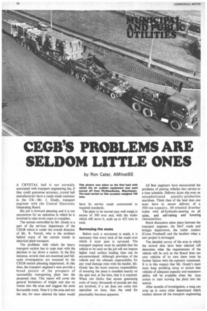
This picture was taken as the first load with which the air cushion equipment was used moved off from Wythenshawe, Manchester. The load carried on this occasion weighed 155 tons.
A CRYSTAL ball is not normally associated with transport engineering but, if they could guarantee accuracy, crystal ball manufacturers have a ready-made customer in the UK—Mr. J. Grady, transport engineer with the Central Electricity Generating Board.
His job is forward planning and it is not uncommon for an operation in which he is involved to take seven years to complete.
The section controlled by Mr. Grady is a part of the services department of the CEGB which is under the overall direction of Mr. R. Farrall, who is the architect behind many of the current trends in electrical plant transport.
The problems with which the heavy transport section has to cope start with the decision to lay down a station. In the first instance, several sites are examined and fullscale investigations are mounted by the CEGB station planning department. At this time, the transport engineer's men provide a broad picture of the prospects .of successfully transporting plant into the proposed sites. This report will cover the general limitations of weight and size on routes into the area and suggest the most favourable route. Note it is the area and not the site, for once selected the latter would have its service roads constructed to required standards, The plant to be moved may well weigh in excess of 300 tons and, with the trailer which will move it, scale up to 425 tons in total.
Surveying the route Before such a movement is made, it is necessary that every inch of the roads over which it must pass is surveyed. The transport engineer must be satisfied that the vehicle to be used on the job will not impose higher road surface loading than can be accommodated. Although provision of the vehicle and the ultimate responsibility for any road damage rests with the haulier, Mr. Grady has the more onerous responsibility of ensuring the piece is installed exactly on the spot and, at the time, that it is required. When one thinks that excess generating costs of many thousands of pounds per day are involved, if a set does not come into operation on time, then the need for punctuality becomes apparent. All fleet engineers have encountered the problems of putting vehicles into service to a time schedule. Delivery d4tes slip even on unsophisticated quantity-production machines. Think then of the lead time one must have to secure delivery of a 300-ton-capacity, 48-wheeled drawbar trailer with all-hydraulic-steering on all axles, and self-raising and lowering characteristics.
Much discussion takes place between the transport engineer, the MoT roads and bridges department, the trailer makers (Crane Fruehauf) and the hauliers when a new project is envisaged.
The detailed survey of the area in which the several sites have been selected will determine what the requirements of the vehicle will be and as the Board does not own vehicles of its own there must be further liaison with the operator concerned. It is in this respect that Mr. Grady's team must keep prodding away to ensure that vehicles of adequate capacity and manoeuvrability will be available when the time comes to start moving the plant into the station.
After months of investigation, a snag can crop up in some other department which renders almost all the transport engineering section's work useless. But there is then nothing for it except to start all over again—which might even mean dreaming up a completely new vehicle.
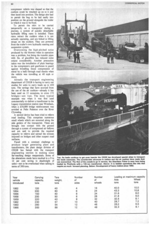
Bigger and bigger A look back at the methods of carrying the pieces since the mid-1950s shows how the need for better vehicle engineering has developed. During the late 1950s the dimensions of the plant began to exceed the capacity of the railway clearance gauge in many cases and so road transport became the sole available method of moving big plant overland.
But the loads kept on getting bigger and by 1966 the optimum size of vehicle from a manoeuvrability point of view had been reached. Limited by the package size, the vehicle, with a capacity of 300 tons, is supported by 48 wheels and imposes 32.3 tons per axle or 8.1 tons per wheel on the road surface when fully laden. There is not at the moment a trailer design which will permit the carriage of loads exceeding 325 tons, although such units are on the drawing boards of the designers. It is envisaged that these units will have 16 axles which, with the bigger loads looming up for the future, will still impose about the same surface loading on roads as do the present 12-axle units.
It was just about at the end of 1966 that the roads and bridges division of the Ministry of Transport introduced a revision of bridge capacities which placed hitherto unknown restrictions on such operations.
The ever-mounting cost of strengthening bridges before a movement were now becoming prohibitive and so the heavy transport section started investigations into the use of the hovercraft principle with the intention of producing a unit that could negotiate bridges without overstressing them.
The Board gave the section carte-blanche to develop, along with the British Hovercraft Corporation, the air-cushion adaptor that is the very latest in heavy transport equipment.
The principle of the hovercraft is too well known for me'to go into details here but the problems that had to be overcome to make the system viable. from a haulage point of view are of considerable interest. The CEGB does not own the transporters it uses; they are hired either from Wynns or Pickfords. The transporters are used for work, other than that of the CEGB and therefore must not be too restricted by their design.
Sealing problems
So the air-cushion equipment had to be constructed in such a way that it could be fitted to several trailers, which also entailed the production of a mobile compressor unit which would be self-transporting and self-contained. Also it had to take account of the unevenness of the normal road surfaces over which it would be required to operate. For instance, the hump found on numerous bridges presented the problem of providing a suitable seal between road and bag, as did cat's-eyes, gulleys and bridge expansion joints, level crossings and the like. And there was the problem of having to lower the overall height of the load when low bridges had to be negotiated. So in addition to being universal, the unit had to be capable of being detached fairly quickly. Rubber was the obvious material for the air container, with steel shoes protecting the area which would come into contact with the ground. A further problem was to ensure that adequate pressure between the shoe area and the ground was achieved without setting up unacceptable drag.
A mock-up was built from which a feasibility study produced all the relevant information necessary for the building of a full-size unit, and this was put in hand.
A compressor vehicle, based on a Commer 16-ton Maxiload chassis, was designed to carry four compressors each powered by a Rolls-Royce 235 bhp petrol engine. Petrol units were specified to keep the weight down.
The light-alloy bodywork on the blower vehicle had to serve two purposes—to house the compressor gear and to carry the bulky cushion. A novel method of carrying the cushion was devised. The rear of the compressor vehicle was shaped so that the cushion could be winched up on to it and then laced into position. The design also had to permit the bag to be laid easily into position on the ground alongside the trailer to which it was to be fixed.
To permit the skirt to be carried temporarily on a transporter during a journey, a system of quickly detachable hydraulic lifting rams is installed. These rams retract the cushion when it is not actually operating, and are linked to lifting straps on the cushion. They are powered from the trailer's own hydraulic steering and suspension system.
Overcoming the high-pitched noise produced by the blowers when in operation was a problem, but lining the transfer pipes with 3in. of glassfibre has reduced noise output considerably. Another precaution taken was the installation of plain bearings in the compressors and gearboxes to guard against brinelling (local compression of metal by a ball) through road shocks when the vehicle was travelling at 40 mph or more.
Already the transport engineering department of CEGB is having to carry out studies for units to carry loads up to 450 tons. The savings that have accrued from the use of the air cushion—already it has been used on 15 occasions, to cross 173 bridges—are vast. The most typical example was when it was first used commercially to deliver a transformer to the Legacy transmission station near Wrexham, when a £30,000 bridge reinforcement was avoided at Felin Puleston over the River Clyweclog.
A second device has been tried to relieve road loading. This comprises numerous small wheels which are mounted along the side girders of the transporter. These are brought into contact with the ground through a system of compressed air bellows and are said to provide the required capacity to relieve and spread the stresses imposed on bridges and other suspect road surfaces.
Faced with a constant challenge to produce larger generating plant and transformers, the plant design division of CEGB has liaised with the transport engineering section in making some far-reaching design reappraisals. Some of the alterations made have resulted in a 9 to 12 per cent saving in deadweight of units—not to be overlooked when talking in terms of 300 tons.