


The Cooling of Two-stroke Oil Engines
Page 68
If you've noticed an error in this article please click here to report it so we can fix it.
TWO-STROKE oil engines have their I own special problems in connection with cooling, mostly arising from the presence of the cylinder ports, in the region of which the cooling is somewhat deficient. A scheme for eliminating this drawback is shown in patent
No. 689,512, which comes from H. List, 126 Heinrichstrasse, Graz, Austria.
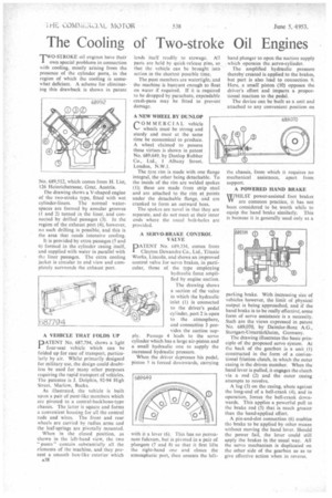
The drawing shows a V-shaped engine of the two-stroke type, fitted with wet cylinder-liners. The normal waterspaces are formed by annular grooves (1 and 2) turned in the liner, and connected by drilled passages (3). In the region of the exhaust port (4), however, no such drilling is possible, and this is the area that needs intensive cooling.
It is provided by extra passages (5 and 6) formed in the cylinder casing itself, and supplied with water in parallel with the liner passages. The extra cooling jacket is circular in mid view and completely surrounds the exhaust port.
A VEHICLE THAT FOLDS UP
PATENT No. 687,794, shows a light four-seat vehicle which can be folded up for ease of transport, particularly by air. Whilst primarily designed for military use, the design could doubtless be used for many other purposes requiring the rapid transport of vehicles. The patentee is J. Dolphin, 92-94 High Street, Marlow, Bucks.
As illustrated, the vehicle is built upon a pair of punt-like members which are pivoted to a central-backbone-type chassis. The latter is square and forms a convenient housing for all the control rods and wires. The front and rear wheels are carried by radius arms and the leaf-springs are pivotally mounted.
When in the closed position, as shown in the left-hand view, the two " punts " contain substantially all the elements of the machine, and they present a smooth box-like exterior which A38 lends itself readily to stowage. All parts are held by quick-release pins, so that the vehicle can be brought into action in the shortest possible time.
The punt members are watertight, and the machine is buoyant enough to float on water if required. If it is required to be dropped by parachute, expendable crash-pans may be fitted to prevent damage.
A NEW WHEEL BY DUNLOP rOMMERCIAL vehicle ‘•—• wheels must be strong and sturdy and must at the same time be economical to produce. A wheel claimed to possess these virtues is shown in patent No. 689,649, by Dunlop Rubber Co., Ltd., 1 Albany Street, London, N.W.1.
The tyre rim is made with one flange integral, the other being detachable. To the inside of the rim arc welded spokes (1); these are made from strip steel and are attached to the rim at points under the detachable flange, and are cranked to form an outward boss.
The spokes are novel in that they are separate, and do not meet at their inner ends where the usual bolt-holes arc provided.
A SERVO-BRAKE CONTROL VALVE
PATENT No. 689,334, comes from Clayton Dewandre Co., Ltd., Titanic Works, Lincoln, and shows an improved control valve for servo brakes, in particular, those of the type employing
hydraulic force amplifled by engine suction.
The drawing shows a section of the valve in which the hydraulic inlet (1) is connected to the driver's pedal cylinder, port 2 is open to the atmosphere, and connection 3 pro vides the suction supply. Passage 4 leads to the servo cylinder which has a large air-piston and a small hydraulic one to supply the increased hydraulic pressure.
When the driver depresses his pedal, piston 5 is forced downwards, carrying with it a lever (6). This has no permanent fulcrum, but is pivoted in a pair of plungers (7 and 8) so that it first lifts the right-hand one and closes the atmospheric port, then unseats the left hand plunger to open the suction supply which operates the servo-cylinder.
The amplified hydraulic pressure thereby created is applied to the brakes, but part is also lead to connection 9. Here, a small piston (10) opposes the driver's effort and imparts a proportional reaction to the pedal.
The device can be built as a unit and attached to any convenient position on the chassis, from which it requires no mechanical assistance, apart from support.
A POWERED HAND BRAKE
WHILST power-assisted foot brakes are common practice, it has not been considered to be worth while to equip the hand brake similarly. This is because it is generally used only as a
parking brake. With increasing size of vehicles however, the limit of physical output is being approached, and if the hand brake is to be really effective, some form of servo assistance is a necessity. Such are the views expressed in patent No. 689,070, by Daimler-Benz A.G., Stuttgart-Unterttirkheim, Germany.
The drawing illustrates the basic principle of the proposed servo system. At the back of the gearbox is a unit (I) constructed in the form of a conventional friction clutch, in which the outer casing is the driven member. When the hand lever is pulled, it engages the clutch via a rod (2) and the outer casing attempts to revolve.
A lug (3) on the casing, abuts against the long-end of a bell-crank (4), and in operation, forces the bell-crank downwards. This applies a powerful pull to the brakc rod (5) that is much greater than the hand-applied effort.
A pin-and-slot connection (6) enables the brake to be applied by other means without moving the hand lever. Should the power fail, the lever could still apply the brakes in the usual way. All the servo mechanism is duplicated on the other side of the gearbox so as to give effective action when in reverse.