


A New Ricardo Two-stroke Oil Engine
Page 54
If you've noticed an error in this article please click here to report it so we can fix it.
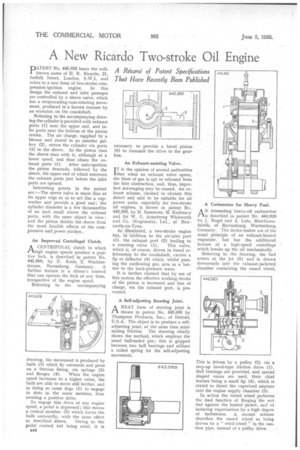
PATENT No. 445,882 bears the wellknown name of H. R. Ricardo, 21, Suffolk Street, London, S.W.1, and refers to a new form of two-stroke compression-ignition engine. In this design the exhaust and inlet passages are controlled by a sleeve valve, which has a reciprocating-cum-rotating movement, produced in a known manner by an eccentric on the crankshaft.
Referring to the accompanying drawing the cylinder is provided with exhaust ports (I) near the upper end, and inlet ports near the bottom of the piston stroke. The air charge, supplied by a blower and stored in an annular gallery (2), enters the cylinder via ports (3) in the sleeve. As the piston rises the sleeve -rises with it, although at a lower speed, and thus closes the ex haust ports (1). After auto-ignition the piston descends, followed by the sleeve, the upper end of which uncovers the exhaust ports just before the inlet ports are opened.
Interesting points in the patent are :—The sleeve valve is made thin at its upper edge so as to act like a cupwasher and provide a good seal; the cylinder diameter is a few thousandths of an inch small above the exhaust ports, with the same object in view ; and the piston Shields the sleeve from the most forcible effects of the compression and power strokes., An Improved Centrifugal Clutch.
ACENTRIFUGAL clutch in which high engine speeds produce a positive lock, is described in patent No. 445,608, by F. Kreis, 2, Wachterstrasse, Nuremberg, Germany. A further feature is a driver's control that can operate the lock at any time, irrespective of the engine speed.
Referring to the accompanying drawing, the movement is produced by balls (3) which fly outwards and press on a friction lining, via springs (2) and flanges (4). When the engine speed increases to a higher value, the balls are able to move still farther, and ip doing so cause dogs (1) to engage in slots in the outer member, thus creating a positive drive.
To engage this drive at any engine speed, a pedal is depressed; this moves a conical member (5) which forces the balls outwardly, with the same effect as described above, Owing to the pedal control rod being axial, it is B94 necessary to provide a bevel pinion (6) to transmit the drive to the gearbox.
An Exhaust-assisting Valve.
IT is the opinion of several authorities that when an exhaust valve opens, the blast of gas is apt to rebound from the first obstruction, and, thus, imperfect scavenging may be caused. An exhaust scheme, claimed to obviate this defect and said to be suitable for all power units, especially for two-stroke oil engines, is shown in patent No. 445,850, by H Sammons, M. Kadenacy and Sir W. G. Armstrong Whitworth and Co. (Engineers), Ltd., of Newcastle-on-Tyne.
As illustrated, a two-stroke engine his, in addition to the air-inlet port (3), the exhaust port (2) leading to a rotating valve (1). This valve, which is, of course, driven in timed relationship to the crankshaft, carries a lip or deflector (4) which, whilst pass-. ing the outflowing gas, acts as a barrier to the back-pressure wave.
It is further claimed that by use of this system the effective working stroke of the piston is increased and loss of charge, via the exhaust port, is prevented.
A Self-adjusting Steering Joint.
ANEAT form of steering joint is shown in patent No. 445,085 by Thompson Products, Inc., of Detroit, USA. The object is to produce a selfadjusting joint, at the same time minimizing friction. The drawing clearly shows the method, which employs the usual ball-ended pin ; this is gripped between two ball bearings and utilizes a coiled spring for the self-adjusting movement. AN interesting heavy-oil carburetter is described in patent No. 444,020 by J. Rugel and A. Lutz, Maschinenfabrik, of Ravensburg, Wurtemberg, Germany. The device makes use of the usual principle of an exhaust-heated vaporizer, but has the additional feature of a high-speed centrifuge which breaks up the oil mechanically.
Referring to the drawing, the fuel enters at the jet (5) and is drawn downwards into the exhaust-jacketed chamber containing the vaned wheel.
This is driven by a pulley (2) via a step-up bevel-type friction drive (1). Ball bearings are provided, and special shaped vanes are used, their chief feature being a small lip (4), which is stated to direct the vaporized mixture into the engine supply chamber (3).
In action the vaned wheel performs the dual function of flinging the wet fuel against the heated jacket, and ef inducing vaporization by a high degree of turbulence. A second scheme describes the vaned wheel as being driven by a " wind-wheel " in the suction pipe, instead of a pulley drive.