


WHY STEAMER COSTS HAVE CHEAPENED.
Page 68
Page 69
If you've noticed an error in this article please click here to report it so we can fix it.
Improvements in Methods of Steam Distribution Make for Economy and Higher Speeds.
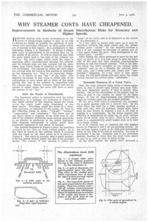
BEFORE dealing with recent developments in the valves of steam-wagon engines it may be as well to discuss as briefly as possible the operation of such valves with particular reference to those points which are of interest in this regard. As a preliminary to this discussion, Figure 1 is important. It shows a simple slide valve in mid-position on its working face, Le., in the middle of its travel. It will be observed that both the ports which lead to the ends of the cylinder are covered. The inner edges, which, when the valve is operating, effect communication between the cylinder and the exhaust pipe, are just covered, but the outer edges, past which steam is admitted to the cylinders, are overlapped. The amount by which the outer edges are covered with the valve in this position is indicated by the dimension (L). That is an important dimension: it is known as the " lap " of the valve. The slightest movement of this valve to either side of its mid-position at once opens one or other of the ports, putting that end of the cylinder in connection with the exhaust pipe. Before, however, either port can be opened to admit steam the valve will have to move the amount of the "lap."
How the Steam is Distributed.
The important points in connection with the steam distribution in a cylinder are indicated in Figure 3. The upper portion of this diagram shows the Crank cir2le, the crank itself being illustrated at one dead centre. Travelling round the circle in a clockwise direction, as indicated by the arrow, we come to the following points in order: "Cut-off," "release," "compression " and "admission." The lower part of the figure shows a diagram of the work done at one end of the cylinder, presuming these various operations to he effected to perfection at the points indicated. This diagram corresponds to others which have previously appeared in this series of articles.
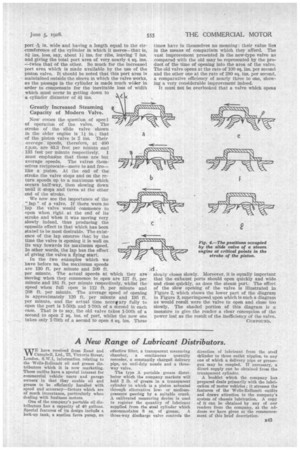
The various diagrams in Figure 4 show the positions occupied by the valve at these critical points. At a the valve is shown in the position which it occupies with the crank on the dead centre as it is shown in Figure 3. The valve is actually open a small amount, it having opened shortly before the end of the previous stroke. The amount of this opening is called the 'lead" of the valve, and it is indicated on the sketch by the dimension 1.
In b the valve is shown fully open as it may be anywhere between the dead centre and the second critical point "cut-off." In the interval between a and b it has changed its direction of motion and at c has again closed the port. This corresponds to the critical point, "cut-off."
After closing, the valve continues to move to the left until, as shown at d, it is just about to open the inner edge of the port, and thus establish communication between it. and the exhaust passage. This is the position which the valve occupies at the critical point "release" and so on, e showing the exhaust ports fully open, and f those ports just closed and " compression " beginning. In g the valve is just about to opep the left-hand steam port once more, the crank having reached the critical point, "admission."
Essential Features 0 a Good Valve.
Now, the most essential thing about a steam-engine valve is that it should open quickly and open wide. The next important quality is that it should close quickly. One of the advantages of the poppet type of valve is that it can readily be made to do these things. It has its disadvantages, too ; otherwise it might be without equal for our present purpose.
So far as a slide valve is concerned, the necessity for a quick opening calls for a narrow port. On the other hand, the need for a wide opening involves a wide port and, with an ordinary simple slide valve such as that shown in Figures 1 and 4, all that is possible is a compromise. In big steam engines this difficulty is surmounted by using two or more narrow ports, all of which open at once. That is not practicable in a comparatively small engine such as is used on a steam wagon.
It is of interest now to compare the two engines shown in Figures 2 and 3 of the previous article. In the old-type engine, a port =" in. wide and presumably about 4 ins, long is all that is available. Its area is practically 2 sq. ins. Probably this is the maximum possible, bearing in mind that the total valve travel is only 1i in., half an inch of which is lap, In the other engine, the piston valve uncovers a
port 196 in. wide and having a length equal to the circumference of the cylinder in which it moves—that is, Si ins, less, say, about 11 ins. for ribs, leaving 7 ins. and giving the total port area of very nearly 4 sq. ins. —twice that of the other. So much for the increased port area which is made available by the use of the piston valve. It should be noted that this port area is maintained outside the sleeve in which the valve works, as the passage in the cylinder is made much wider in order to compensate for the inevitable loss of width which must occur in getting down to a cylinder diameter of 4i ins.
Greatly Increased Steaming Capacity of Modern Valve.
Now comes the question of speed of operation of the valve. The stroke of the slide valve shown in the older engine is 11 in.'' that of the piston valve is 2 ins. Their average speeds, therefore, at 400 r.p.m. are 83.3 feet per minute and 133 feet per minute respectively. I must emphasize that these are but average speeds. The valves themselves reciprocate—move to and fro— like a piston. At the end of the stroke the valve stops and on the return speeds up to a maximum which occurs half-way, then slowing down -until it stops and turns at the other end of the stroke.
We now see the importance of the " lap " of a valve. If there were no lap the valve would commence to open when right at the end of its stroke and when it was moving very slowly indeed, thus producing the opposite effect to that which has been stated to be most desirable. The existence of the lap ensures that by the time the valve is opening it is well on its way towards its maximum speed. In other words, the lap has the effect of giving the valve a !lying start.
In the two examples which we have before us, the maximum speeds are 130 ft. per minute and 209 ft. per minute. The actual speeds at which they are moving when they commence to open are 127 ft. per minute and 181 ft. per minute respectively, whilst the speed when full open is 112 ft. per minute and 208 ft. per minute. The average speed of opening is approximately 120 ft. per minute and 195 ft. per minute, and the actual time necevary fully to open the port is 1-50th and 1-70th of a second in each ease. That is to say, the old valve takes 1-50th of a second to open 2 sq. ins, of port, whilst the new one takes only 1-70th of a second to open 4 sq. ins. These times have in themselves no meaning: their value lies in the means of comparison which they afford. The vast improvement presented in the new-type valve as compared with the old may be represented by the product of the time of opening into the area of the valve. The old valve opens at the rate of 100 sq. ins, per second and the other one at the rate of 280 sq. ins, per second, a comparative efficiency of nearly three to one, showing a very considerable improvement indeed.
It must not be overlooked that a valve which opens
slowly closes slowly. Moreover, it is equally important that the exhaust ports should open quickly and wide and close quickly, as does the steam port. The effect of the slow opening of the valve is illustrated in Figure 2, which shows the lower part of the diagram in Figure 3, superimposed upon which is such a diagram as would result were the valve to open and close too slowly. The shaded portion of this diagram is a measure to give the reader a clear conception of the power lost as the result of the inefficiency of the valve.