


A FOWLER TAR-SPRAYING MACHINE.
Page 40
If you've noticed an error in this article please click here to report it so we can fix it.
A Resume of Recently Published Patents.
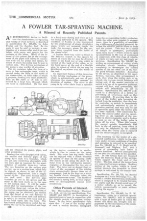
AN INTERESTING device to facilitate the simultaneous tar-spraying and rolling of riid surfaces is described in specification No. 196,072, by John Fowler and Co. (Leeds), Ltd. -In • the main it may be said' to embody a combination of a steam-roller and.-a-tar container with pump and sprays for the contents of the latter. Much of the in' tercet of this patent lies in the arrangement of the pipes and valves in connection with the tar pump and sprays; by means of which the pump may be put to various uses: The driving mechanism of the pump is also worthy ofattention.
The tar container takes the form of a more or less rectangular tank, which is carried under the belly of the boiler of the steam-roller, on both sides of which it projects, forming two small platforms. That onthe right or off side is perforated by a large hole, through which the tank is replenished. On the near side are situated the pump, pipes, and other accessories. .
Dealing first with the pipes and valves, the suction and delivery pipes of the pump, have each two branches, which are put into connection alternately with the main pipe as required, by the manipulation of suitable three-way valves. The two branches on the suction pipe are led, one to a suction hose, which may be dipped, as shown in one of the accompanying illustrations, into a supply barrel of. tar.. The other branch enters the tank itself. The delivery pipe branches go one to the _sprays and the other to the tank itself, as in the case of the suction pipe. It will be understood that bymanipulation of the two controlling three-way valves the following various conpections and operations of the pump can be obtained : (a) suction from the barrel of tar and delivery to tank; (b) suction from tank and delivery to spray; (c) suction from tank and delivery back again into the tank. The last-named arrangement is useful for enabling the tar to be circulated and kept in a fluid, state during such time as it is not being delivered to the sprays. This condition of fluidity is also maintained by the employment of steam circulating pipes, which aremaunted inside the tank, the necessary steam for the purpose being sof:plied from the boiler of the steam-roller.
A further three-way valve is fitted in the delivery branch to the sprays by means of which the tar may be diverted either to the fixed row of jets, which is carried at the back of the roller, or to the hand spray at the end of a flexible pipe, by means of which the tar may be distributed anywhere over the width of the road. . . .
An important feature of this invention is the driving mechanism a the .pump, which is automatically put out of gear whenever the steam-roller reverses its direction of motion. The drive to the pump is by roller chain from a sprocket
on the engine crankshaft to anotbc which is free to rotate on the pump shaft. The latter has dog teeth, which can be engaged with a clutch mounted on :splines or keys on the pump shaft. The clutch is slid along the shaft by a hand lever in the well-known manner, engaging or disengaging the two sets of dogs. The latter are so shaped that reversal of the movement of the driving chain automatically throws them out of engagement, just as the dogs on a starting handle clutch disengage when the engine commences to run. The handle of the clutch is spring held, so that engagement or disengagement cannot occur accidentally.
Other Patents of Interest.
The Metropolitan-Vickera Electrical Co:, Ltd., devote two specifications, Nos. 186,327 and 189,777, to descriptions of improved control gear in connection with the electric motors of trackless trolleybuses. In the hitter specification they state that "if one of the trolley poles of such a vetiicle becomes disengaged
from the corresponding trolley conductor, -while the other pole remains in engagement, there is a possibility of establishing. a-differeace elelectricalpotential between the Metallic 'vehicle frame or body and the ground. This may be a source' of danger to passengers, particularly upon -rainy days '!---which seems to open up possibilities in the way of excitement in connection with this class of vehicle, of which we have not yet had much ex, perience. Specification No. 186,327 describes an arrangement of wiring which ernbodies circuit breakers designed completely to de-energize the control system of the car when one of the trolley poles becomes detached. According to-the device, as described in the specification, however, this arrangementl is such, that when the trolley pole isreplaced, tbe Various circuit breakers will recluse and, if the mastercontroller or switch is in one of its operative positions, current will flow, and, presumably, the vehicle will immediately be set in motion. Specification No. 189,777 is devoted to a description of a device for preventing an occurrence such as that just suggested. It provides that, in the event of the trolley pole becoming detached from its conductor, that the master controller or switch is immediately and automatically returned to the inoperative position, and may only be put in operation again-after the trolley pole hass beenreplaced.' -Theconnection between the control pedal and the operating lever on the camshaft of the controller is electro-magnetic, and is broken so soon as one of the trolleypoles is taken off its wire. When this occurs, the control spindle immediately flies back to the off position, from which it can only be displacedl by the control pedal when the trolley pole is replaced and the electro-magnet re-energized.
.The .tendency for the trailer of a sixwheeled combination vehicle to tip sideways under certain conditions of loading and operation is referred to in specification No. 196,824 by P. G. Hugh and G. Scam-nen and Nephew, Ltd., and a means of preventing such action is therein described.. Several arrangements of the idea are embodied in the specification. In one torque bars are mounted upon the trunnion block of the springs, which support the front end of the trailer. The free ends of the torque bars are supported between springs. Rocking motion of the trailer, which is transmitted through the turntable to these springs, is restrained by the torque bars.
Specification No. 181.710, by Societe Anonyme derkuto Debrayage'T.L., deScribes a ratchet transmission mechanism which is designed tobe located between the engine and the change-speed gear of a motor vehicle, so as to permit the vehicle automatically to coast without turning the engine..
Specification No. 196,643, by F. W. Lanchester, refers to a, previous specification, No. 166,017, and is concerned with a type of brake gear in which the drums and shoes are brought into engagement by the movement,of the eccentric bearings of the axle.