


Patents Completed.
Page 26
If you've noticed an error in this article please click here to report it so we can fix it.
Complete specifications of the following patents will he sent to any address in the United Kingdom by the Sales Branch, Patent Office, Holborn, W.C., upon receipt of eightpence per copy.
Bosch Automatic Timing.
Firm of Robert Bosch, No. 24,665/1912, dated under the International Convention 6th December, 1911.—The tieing at ignition of internal-combustion eines is automatically adjusted accordMg to the speed by means of an adjustable coupling between the armature shaft on the magneto and the driving shaft. What is required is to produce a relative movement of the two shafts as the speed increases, Two discs are mounted upon the armature shaft and driving shaft respectively, and the space between them is occupied by a number of plates or sectors which are free to move radially under centrifugal action as the speed increases. A series of pins is arranged parallel to the shaft and round about it extending from one disc to the other. One of these pins is fixed on the right-hand or armature disc, and the next pin is fixed on the driving disc. The other pins are mounted at each end in circular slots in the two discs so that they can travel round. The inertia masses are a series of sector plates, each with two radial slotss engaging two ad jaeent pins. Alternate layers of these plates are staggered, so that if a plate on the first layer engages the first and second pins, a plate on the next layer engages the second and third pins, but the two pins fixed in the discs are not coupled together. When the inertia masses move outwards under centrifugal force, since the slots are radial, the pins are caused to approach one another. This action is a cumulative one from the first fixed pin right round the circle to the other fixed pin, so that one disc is moved relatively to the other and the necessary adjustment of the ignition time is obtained. A spring surrounds the inertia masses and provides a means for controlling them.
A New Form of Differential.
G. M. Hartley, No. 7473, dated 27th March, 1912.—This specificsition describes a driving gear for motor vehicles which will serve the purpose of the differential, but is much cheaper. It con slats essentially of a ratchet-and-pawl drive which will transmit power either in clockwise or anti-clockwise direction, but will, at the same time, permit overrunning in either direction, one of these devices being used on each wheel. The interior of the brake drum is provided with teeth, and a double pawl is pivoted
on a disc loose on the axle, but is held frictionally against the side of the brake drum, so that it tends to be carried round with it. The pawl embraces one end of an actuator which is keyed on to the shaft. This is provided with shoulders to engage the pawl and transmit the drive through it to the teeth on the brake drum. Near these shoulders on the actuator are knees which, when the pawl is moved round relatively to the actuator, move it into an intermediate position where it does not engage with the teeth on the brake drum. Whei, the differential is in use, the wheel travelling on the shorter path has the drive maintained on it, but the other wheel overruns the driving shaft and the actuator. The disc on which the pawl is mounted, is carried round frictionally by its engagement with the wheel and the knees on the actuator engage the pawl and bring its operative end out of action. In order to prevent, its being carried beyond this position, the motion of the friction disc relatively to the driving shaft and actuator, is limited by a pin in the axle working in a radial slot in the disc as shown.
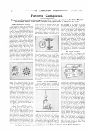
Saurer Change-speed Gear.
Firm of Adolph Saucer, No. 2280/13, dated under International Convention, 15th April, 1912.—The particular feature of this invention is that all the coupling rods between the change-speed lever and the gearbox are positively locked by a tail piece on the changespeed lever, except the particular rod with which the lever is engaged. The accompanying drawing shows in section the locking, device as for three rods. It consists of balls working in a pocket, and arranged to be pressed by springs into recesses in the rods. The balls themselves are held down by plungers on which are spindles projecting through the top of the casing. The change-speed lever is provided with curved tail pieces which project over and engage the spindles of the locking mechanism so as to prevent the balls being lifted unless the spindle is opposite the gap between the two tails on the hand lever. The lever is arranged to operate in an ordinary gate, in which it is moved transversely to engage the ball on the lower end with the particular connecting rod required. The gap between the leasing tail pieces is opposite this ball, so that the coupling rod which is engaged for operation by the hand lever is the only one on which the locking mechanism is released.
An Argyll Gearbox.
H. Perrot, and J. S. Matthew, Nn. 9796, dated 26th April, 1912.—This gearbox is so arranged that it occupies a minimum of space, and no gears are running idly in the neutral position or on top speed. The driving-shaft on the left
hand side is in alignment with the driven shaft on the right, and a lay shaft is arranged below them. The driving-shaft carries a eliding gearwheel on the left and a loose wheel, which can be clutched to it by a dog-clutch, on the right-hand end, The driven shaft also carries a loose wheel on its right-hand end and a double dog-clutch, which can lack this wheel to the shaft, or can lock the driving and driven shafts together. The lay shaft carries four gearwheels fixed on it, one for each of the three wheels already mentioned, and the fourth for the reverse. The two clutches on the driving and driven shafts are coupled together so that they move in unison. To obtain the first speed the sliding gear on the driving shaft is moved to the left, and transmits the drive through the lay shaft to the gearwheel which is clutched on the driven shaft. The second speed is obtained by putting in the clutch on the driving shaft so that the drive is transmitted through the gearwheel on the right-hand end of this shaft, the lay shaft, and the gearwheel on the driven shaft. The top speed is obtained by coupling the two shafts together directly, and the reverse by an additional gearwheel not shown in this figure, which engages the second wheel from the left on the lay shaft.