


A CHANGE OVER GEAR.
Page 32
If you've noticed an error in this article please click here to report it so we can fix it.
A Résumé of Recently Published Patents
In describing the lloyal Show exhibits last week we made particular reference to the change-over gear which was a prominent exhibit on the stand of John Fowler and Co. (Leeds), Ltd., and which was, moreover, entered by them as a new implement, being actually awarded the silver medal. The invention is of particular interest to municipal engineers and road contractors, and no doubt, therefore, the following particulars and accompanying illustrations, which are taken from specification No. 163,490, will have special interest for many of our readers.
The gear which is designated by this somewhat curious appellation is really an arrangement whereby a steam road roller may quickly and easily be converted to a traction engine and vice versa. •
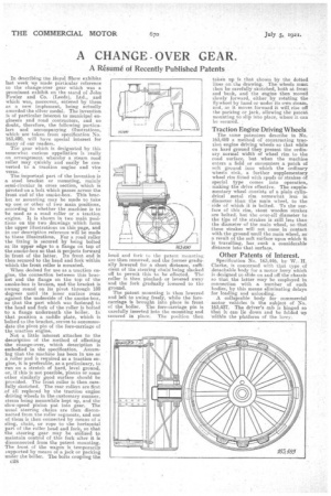
The important part of the invention is a steel bracket or mounting, mainly semi-circular in cross section, which is pivoted on a bolt which passes across the front end of the smoke-box. This bracket or mounting may be made to take up one or other of two main positions, according to whether the machine is to be used as a road roller or a traction engine. It is shown in two main positions on the two drawings which form the upper illustrations on this page, and in our description reference will be made to these illustrations. For a road roller the fitting is secured by being bolted at its upper edge to a flange on top of the smoke-box so that it projects forward in front of the latter. Its front end is then secured to the head and fork within which the front roller is mounted.
When desired for use as a traction engine, the connection between this bracket and the flange on the top of the smoke-box is broken, and the bracket is swung round on its pivot through 180 degrees until its inner surface rests against the underside of the smoke-box, so that the part which was fastened to the head and fork of the roller is bolted to a flans!) underneath the boiler. In that position a saddle plate, which is bolted to the bracket, serves to accommodate the pivot pin of the fore-carriage of the traction engine.
Not a little interest attaches to the description of the method of effecting the change-over, which description is embodied in the specification. Assuming that the machine has been in use as a roller and is required as a traction engine, it, is preferable, as a preliminary, to run on a stretch of hard, level ground, or, if this is not possible, planks or some other similarly good surface should be provided. The front roller is then carefully skotched. The rear rollers are first of all replaced by the traction engine driving wheels in the customary manner, steam being meanwhile kept up, and the slow-speed pinion put into gear. The usual steering chains are then disconnected from the roller segments, and one of them is then connected by means of a sling, chain, or rope to the horizontal part of the roller head and fork, so that the steering gear may be utilized to maintain control of tins fork after it is disconnected from the patent mounting. The front of the wagon is temporarily supported by means of a jack or packing under the boiler. The bolts coupling the 028
head and fork to the patent mounting are then removed, and the former gradually lowered for a short distance, sufficient of the steering chain being slacked off to permit this to be effected. The roller is then pinched, or levered away and the fork gradually lowered to the ground.
The patent mounting is then lowered and left to swing freely, while the forecarriage is brought into place in front of the boiler. The fore-carriage pin is carefully inserted into the mounting and secured in place. The position then
taken up is that shown 16, the dotted lineson the drawing. The wheels must then be carefully skotched, both at front and .back, and the engine then moved slowly forward, either by rotating the flywheel by hand or under its own steam, and, as it moves forward it will rise off the packing or jack, allowing the patent mounting to slip into place, where it can be secured. •
Traction Engine Driving Wheels
The same patentees describe in No. 163,489 a method of constructing traction engine driving wheels so that while on hard ground they present the ordinary normal width of wheel rim to the road surface, but when the machine enters a field or encounters a patch of soft ground into which the ordinary wheels sink, a further supplementary wheel rim fitted with spuds or strakes of special type comes into operation, making the drive effective. The supplementary wheel consists of a plain cylindrical metal rim somewhat less in diameter than the main wheel, to the side of which it is bolted. To the surface of this rim, stout wooden strakes are bolted, but the over-all diameter to the tips of the strakes is still less than the diameter of the main wheel, so that these strakes will not come in contact with the ground until the main wheel, as a result of the soft surface upon which it is travelling, has sunk a considerable distance into that surface.
Other Patents of Interest.
Specification No. 163,446, by W.-. H. Clarke, is concerned with that type of detachable body for a motor lorry which is designed to slide on and off the chassis so that the latter may be employed in connection with a number of such bodies, by this means eliminating delays for loading and unloading. A collapsable body for commercial motor vehicles is the subject of No. 163,437. The driver's cab is hinged .so that it' can lie down and be folded up 'within the platform of the lorry.