


Patents Completed.
Page 22
If you've noticed an error in this article please click here to report it so we can fix it.
LIFTING JACKS. — Austin. — No. 10,280, dated 27th April, 1910.—This invention relates to that type of lifting jack in which the lifting bar can be raised by hand, when the jack is not loaded, BO as to save time in winding it up with no load on it, and similarly in lowering it without a load. The general arrangement is that the pinion meshing with the rack on the lifting pillar is arranged in bearings, which are hinged to the istandard. By suitably tilting the casing, this pinion is thrown out of gear with the rack, which can then be adjusted as required without loss of time. The casing for the gear is formed as two cheeks, which are hinged on to the main pedestal by a pin, and in which are fixed the bearings for the pinion meshing with the rack and for the worm gear and its shaft. A curved slot is provided to limit and to guide the motion of lifting the pinion clear of the rack ; it is of such dimension as to allow the pinion to be moved just clear, but not further than is convenient to give the necessary clearance. When the bar is to be dropped, the frame containing the gear is tilted to clear the pinion from the rack, when the bar immediately falls by its own weight. It is preferred to enclose the worm wheel and gear with a sheet metal case, and this is conveniently effected by shaping the plate to form the inner side of the case and by fixing the sheet metal as a cap thereto.
SELF-PROPELLED lEf ARROW.—Ver• mood and Zuellennec.—No. 8,839 of 1910. —Dated under International Convention 30th April, 1909.—This invention relates to self-propelled harrows or diggers of the type described in Application No. 8,838 of 1910, and it is more particularly concerned with the arrangement for varying the depth to which the revolving tines are made to penetrate. These tines or diggers are attached to an axle carried by two movable links suspended from the frame of the vehicle. A rack is attached to a vertical rod provided with a suitable spherical beating in the link. A pinion is driven from the motor through friction wheels, so as to provide power for shifting the diggers. There is also described an indicating device, driven from the same shaft as the pinion, to show the depth to which the tines are arranged. This enables the driver to reset the mechanism to the same depth after it has to be adjusted in order to avoid obstacles too solid to be cut through, or in order to cross a road, or to overcome similar difficulties.
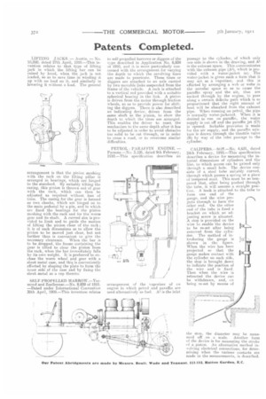
PETROL • PARAFFIN ENGINE. — Parsons.—No. 3,126, dated 9th February, 1910.—This specification describes an arrangement of the vaporizer of an engine in which petrol and paraffin are used alternatively as fuel. Al is the inlet passage to the cylinder, of which only one side is shown in the drawing, and As is the exhaust space. This communicates with the exhaust pipe (AS), which is provided with a water-jacket (a). The water-jacket is given such a form that it may act as a vaporizer, and this is effected by arranging a web or webs in the annular space so as to cause the paraffin spray and the air, that are sucked through by the engine, to pass along a certain definite path which is so proportioned that the right amount of heat will be absorbed from the exhaust pipe. When running on petrol, the pipe is normally water-jacketed. When it is desired to run on paraffin, the water supply is cut off and the paraffin jet (Cl) is opened. Suitable provision is made for the air supply, and the paraffin mixture is drawn through the throttle valve () by way of the inlet passage to the cylinder.
the stop, the diameter may be measured off on a scale. Another form of the device is for measuring the stroke rif a piston. An alternative method involving electrical connections, for determining when the various contacts are made in the measurements, is described.