


Self-adjusting King Pins
Page 86
If you've noticed an error in this article please click here to report it so we can fix it.
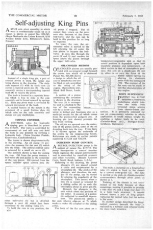
ASTUB axle pivot assembly in which wear is automatically taken up as it occurs is shown in patent No. 826,245. (Regie Nationale des Usines Renault, 8/10 Avenue Emile Zola, Billancourt, Seine, France.)
Instead of a single king pin, a pair of coaxial pivots is used, the upper one being shown in the drawing. The stubaxle support (1) with its track • arm (2) carries a tapered pivot pin (3). The axle assembly carries a corresponding tapered bush (at) to receive the pivot.
The bush is located in a separate housing which is free to slide in the axle assembly and is forced upward by springs (5). Thus any pivot wear is corrected by upward movement of the bush.
A second feature of the patent is the provisiori of a small friction shoe (6) which rubs" on the axle assembly and damps out any oscillations. . .
TIPPING CONTROL
A CONTROL valve for hydraulic tipping gear is described in patent
No. 817,859. The valve is controlled by compressed air and will stop and hold the body in any position by forming a hydraulic lock. (Tatra Narodni Podnik, Koprivnice, Czechoslovakia.) The layout is shown diagrammatically in the drawing. An oil pump (1) provides the pressure for the ram (2) which lifts the body. The central control valve is actuated by a small air servo (3).
The position shown is that for raising the ram. Oil from the pump unseats a ball-valve (4) and passes to the underside of the yarn piston'. Oil ejected from the upper cylinder space cannot pass the oil pump is stopped. The oil cannot then return on the pressure side because of the lower ball-valve, and the ram can be held in this position for as long as required.
To lower the ram, the airoperated valve is moved to the left allowing the oil under the ram piston to by-pass the ballvalve. i does this through the ports (8 and 9) and reaches the space above the piston through the upper ball-valve.
OIL-COOLED PISTONS
nIL-COOLED pistons are usually pro vided with an integral trough beneath the crown into which oil is delivered. Patent No. 825,406' shows a design in which the oil _tray is detachable and can be fitted or not, according to the rating of the engine. (Specialloid, Ltd., Black Bull Street, Leeds, 10.) A section at a piston embodying the invention is shown in the drawing. The tray (I) is rectangular and is attached to 'the top of the connecting rod by a screw (2). The screw is drilled and functions also as a multi-jet nozzle for the oil which comes from the pressure-fed gudgeon pin. A locating pin (not shown) prevents the tray from turning.
The oil jets are sprayed over the underside of the piston crown, some of the oil dropPing back into the tray. From there it is thrown against the underside of the crown by the reciprocating forces. References are made to earlier patents numbered 617,224 and 724,354.
INJECTION PUMP CONTROL
rAA PETROL-INJECTION pump is the subject of patent No. 817,719. The pump incorporates a control member which regulates the output automatically and is controlled by manifold pressure and other variables. (Bendix Aviation Corp., South Bend, Indiana, U.S.A.) Referring to the drawing, the pump plungers (1) are spaced around a circle and reciprocated by a swashplate (2). The stroke of the plungers, and therefore the output of the pump, can be varied by altering the angularity of the swashplate. This occurs when a link (3) is raised or lowered by a sliding collar (4) to rock the swashplate about its pivot pin (5).
Beneath the plungers is the unit which alters the position of the collar, It consists of a piston (6) subjected to manifold depression. The piston-rod carries a flat cam (shown edge-on at 7) which works a rocker (8) coupled to the sliding collar.
The back of the flat cam abuts on a temperature-responsive unit so that its actual position is dependent upon both manifold pressure and temperature,. A third variant is that of atmospheric pressure; this acts on a diaphragm (9) a-nd its effect is to vary the force of the piston return spring by altering its abutment point with the sliding ,rod (10). The contour of the flat cam can be made to suit the characteristics of any engine.
BODY SUSPENSION DATENT No. 817,94/ I describes a bodywork underframe which iniulates the body from torsional stress arising from chassis-frame dis tortion. It is primarily intended for use on cross-country vehicles in which application it could reduce weight by enabling a lighter body to be used. (Daimler-Benz A.G., Stuttgart-Untertdrkheirn, Germany.) The body is mounted on a longitudinal tube (1) which is fixed to the chassis by a central cross-girder (2). The tube is carried at its ends on chassis-mounted cross-members through pivot joints ' as 'shown at 3.
Twisting of the chassis is not tran3mitted to the body because of these mountings, making it possible to provide a side door (4) and a large rear door (5) in a light body structure.' A second scheme shows a pair of long girders replacing the central tube, but the action is the same.
In another design described the longitudinal member beneath the body is replaced by a tubular tank situated inside the main body structure. ,