


Pumping Equipment for Tankers
Page 72
If you've noticed an error in this article please click here to report it so we can fix it.
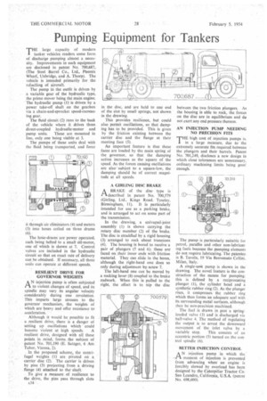
THE large capacity of modern tanker vehicles renders some form of discharge pumping almost a necessity. Improvements in such equipment are disclosed in patent No. 700,687, (The Steel Barrel Co., Ltd., Phcenix Wharf, Uxbridge, and A. Thorp). The vehicle is intended primarily for the refuelling of aircraft.
The pump in the outfit is driven by a variable gear of the hydraulic type, the prime mover being the main engine. The hydraulic pump (1) is driven by a power take-off shaft on the gearbox via a chain-and-sprocket speed-increasing gear.
The fluid circuit (2) runs to the back of the vehicle where it drives three direct-coupled hydraulic-motor and pump units. These are mounted in line, only one being visible at 3.
The pumps of these units deal with the fluid being transported, and force it through air eliminators (4) and meters (5) into hoses coiled on three drums (6).
The hose-drums are power operated, each being belted to a small oil-motor, one of which is shown at 7. Control valves are included in the hydraulic circuit so that an exact rate of delivery can be obtained. If necessary, all three units can operate at different speeds.
RESILIENT DRIVE FOR GOVERNOR WEIGHTS
A N injection pump is often subjected
to violent changes of speed, and its spindle may vary its angular velocity considerably during one revolution. This imparts large stresses to the governor mechanism, the weights of which are heavy and offer resistance to acceleration.
Although it would be possible to fit a resilient drive, there is a danger of setting up oscillations which could become violent at high speeds. A resilient drive, designed with all these points in mind, forms the subject of patent No. 701,190 (E. Satzger, 6 Am Tabor, Vienna, 2).
In the proposed scheme, the centrifugal weights (1) are pivoted on a carrier disc (2). The carrier is driven by pins (3) projecting from a driving flange (4) attached to the shaft.
To give a measure of resilience to the drive, the pins pass through slots A34 •
in the disc, and are held to one end of the slot by small springs, not shown in the drawing.
This provides resilience, but could also permit oscillations, so that damping has to be provided. This is given by the friction existing between the carrier disc and the flange at their meeting face (5).
An important feature is that these faces are loaded by the main spring of the governor, so that the damping action increases as the square of the speed. As the forces causing oscillations are also ' subject to a square-law, the damping should be of correct magnitude at all speeds.
A GIRLING DISC BRAKE A BRAKE of the disc type is rldescribed in patent No. 700,579 (Girling, Ltd., Kings Road, Tyseley, Birmingham, 11). It is particularly intended for use as a parking brake, and is arranged to act on some part of the transmission.
In the drawing, a univelsal-joint assembly (I) is shown carrying the rotary disc member (2) of the brake. The disc is straddled by a rigid housing (3) arranged to rock about trunnions (4). The housing is bored to receive a pair of plungers (5 and 6); these are faced on _their inner ends with friction material. They can slide in the bores, although the right-hand one does so only during adjustment by screw 7.
The left-hand one can be moved by a rocking lever (8) coupled to the brake rodwork. When this is pulled to the right, the effect is to nip the disc between the two friction plungers. As the housing is able to rock, the forces on the disc are in equilibrium and du not exert any end pressure thereon.
AN INJECTION PUMP NEEDING NO PRECISION FITS
THE high cost of injection pumps is, in a large measure, due to the extremely accurate fits required between the plungers and their barrels. Patent No. 701,249, discloses a new design in which close tolerances are unnecessary, ordinary machining limits being goo(' enough.
The pump is particularly suitable for petrol, paraffin and other non-lubricating fuels because the pumping elements do not re9uire lubricating. The patentee is B. Tavola, 19 Via Benvenuto Cellirti. Milan, Italy.
A single-unit pump is shown in the drawing. The novel feature is the construction of the means for pumping; this is defined by a reciprocating plunger (1), the cylinder head and a synthetic rubber ring (2). As the plunger rises, it compresses the rubber ring which then forms an adequate seal with its surrounding metal surfaces, although they be non-precision machined.
The fuel is drawn in past a springloaded valve (3) and is discharged via ball-valve 4. The method of regulating the output is to arrest the downward movement of the inlet valve by a variable stop. This consists of an eccentric portion (5) turned on the control spindle (6).
BETTER INJECTION CONTROL
AN injection pump in which the
moment of injection is prevented from advancing when an engine is forcibly slowed by overload has been designed by the Caterpillar Tractor Co. San Leandro, California, U.S.A. (patent No. 698,600).