


AN ew V Engine
Page 60
If you've noticed an error in this article please click here to report it so we can fix it.
A Resume of Patent Specifications that Have Recently Been Published
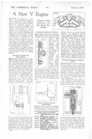
I NTEREST is growing in " pan.cake " and other forms of engine in which compactness is the outstanding feature; such a power unit by DaimlerBenz A.G., Stuttgart, Germany, is described in patent No. 959,032. The sectional drawing shows the salient features, which include two rows of cylinders set at 120 degrees to each other, and a lowermost connecting wall (3) which forms part of the frame. The crankshaft runs in bearings 1, whilst a similar pair (2) is provided for the two camshafts. A lower bore (4) forms a tunnel enabling the tra.nsmisthen shaft to be passed through the whole engine, whilst provision is made for all auxiliaries to be mounted within the general outline of the unit.
The cylinders are totally enclosed, and whilst water cooling may be used if desired, it is preferable to employ a forced draught of air for cooling purposes.
Steering Arrangement for Three-wheelers.
IljUITH light vehicles of the singleVV front-wheel type, difficulty is sometimes experienced when wheel changing, owing to the presence of the forks. To avoid this, and at the same time to provide a sturdy yet light construction, is the object of the scheme shown in patent No. 458,685 by County Commercial Cars, Ltd., and E. T. Tapp, both of Upper Street, Fleet, Hants.
In this design, a. single half-fork (6), terminating in a rubber-bushed boss
(2) is used. A shaft (3) carries a spring-arm (4) at one end, passes through the rubber bush, and then
forms the wheel spindle. The lastnamed is not concentric with shaft 3, but is set back a short, distance, and in conjunction with spring 5 forms the suspension system. The weight of the vehicle and the pull of the spring being in equilibrium, there is no sideways tilting force on the rubber bush. The steering head is fixed in a large tubular cross-member. (1), which is ingeniously made to act also as a petrol tank,
B46 Avoiding Overheating of Clutches.
BY constant research and experiment the modern clutch has been reduced to small dimensions, whilst the trans
mitted horse
458.95'2 power has prob ably been in
creased; this naturally tends towards higher working temperatures, and the problem of cooling has of late arisen.
Patent No.
958,952 from Roper and Wreaks, Ltd., and P. Heard, Oval Works, Sheffield, shows a clutch design in which two devices are employed to assist cooling. The first is a thin aluminium annulus (1) which is kept in contact with the pressure plate on its outer rim, the inner portion being in free air. The second is the use of thin tubes (2) as spring linings; these may be perforated or scooped on the ends.
Using the Exhaust Gas for Supercharging.
EXHAUST gases possess considerable kinetic energy, and thus any useful work performed by them results in a definite increase in overall thermal efficiency. An attempt to use the kinetic energy for inducing a 4egree of supercharge -in the intake is shown -in patent No. 458,613 by G. l. Glasspoole, B.Sc., 37, Portland Road, Rugby. This scheme employs a vessel (2) which may also functicn as a silencer. The engine exhau t is fed from the jet (5) of an injector (9), and enters the vessel carrying atrrospheric air with it, after the manner of a Bunsen burner. Separation of the two constituents is, the inventor states, brought about by their temperature difference, the hot gases leaving by the upper vent (1), whilst the c oler air is forced into the engine air in e (3).
Housing the Filter of an Inj ction System.
FILTRATION of oil fuel is always a vital necessity, and it is preferable to locate the filter as close to the nozzle as possible, in order that foreigi in the pipe line shall not pol
fuel after filtration. In pa 458,551 an injector is shown the filter is internally housed, but an inch or two from the s The patentee is Adolphe Sa Arbon, Switzerland.
The drawing shows the sc which the injector is housed i in the cylinder head, a cap holding the assembly in place; matter ute the nt No. which and is ray tip. rer, of
eme in a bore ut (1) includ
ing the spherical-ended supp (5). In this case the filter is a b provided with fine, lengthwise in its outer surface, alternate y connected with an inlet and an outlet. (Patent No. 185,402.) The fuel enters the filter at the top and pas es into central space 4 via small cro s passabes (3).