


RUBBER BUSHES FOR SHACKLES.
Page 34
If you've noticed an error in this article please click here to report it so we can fix it.
A Résumé of Recently Published Patent Specifications.
r-FIEE use of rubber under pressure for bushes in parts .1 where a limited oscillation takes place is: already well known. In patent No. 303,260, G. A. Woocillead claims to have obtained an advantage over the usual, construction where such hushes are used. The specification points out that unless both inner and outer sheaths of the bush be seeured firmly, so that any movement is confined to the twisting of the rubber, the object is defeated, for should movement take place between metal parts lubrication becomes necessary and wear will occur.
To prevent movement between the outer sheath and the eye of the spring the latter is made with a flat portion as showu. it is evident that -where such a bush is used the eye of the spring must be larger than usual, consequently there is more probability of its opening out under load. To prevent this from happening the eye is made with more than one coil.
No mention is made of any special means for securing the inner sheath from moving on its piu.
The Grinding of Gear Teeth to Produce Silent Running.
SILENT .gears are now becoming an essential feature of all vehicles which are destined to carry passengers. Efforts in the direction of " faked " tooth forms, " dopes," etc., having_ proved themselves futile, those who wish to produce silent-running gears have arrived at the conclusion that the true remedy for noisy gears lies in the production of an absolutely true tooth form, which can only be produced by grinding the teeth after hardening.
This being the position, it should be of interest to the industry to consider the latest steps that have been taken in the direction of accurate and economical gear-grinding methods.
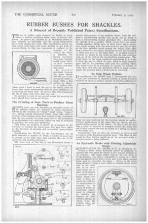
Specification No. 2'73,127, by the Lees-Eradner Co., of Ohio, describes a machine in which a number of gears can be ground at 013 same time, thus reducing the cost of the operation and ensuring accuracy. " The large view on the left of our
illustration shows a general arrangement of the machine where, from the bed, rises a non-revolving spindle .(A), at the top at which is fixed a non-revolving master gearwheel (B). Surrounding the spincll.) A is a member which mrries four (or more). upright spindles, which carry at their lower end a master gear which meshes with the. non-revolving gear B, so that,. as the four spindles travel around the master gear, they have a planetary movement, travelling around and revolving cm their own axes at the same time. A grinding wheel is situated, as shown in all views, so that its edge coincides with one of the teeth of the non-revolving master gear. The small views on the right, numbered respectively 1, 2, 3 and 4, show the way in which the gear which is being operated upon rolls in its planetary path past the grinding wheel. The master gear is so arranged, as regards its number of teeth, that each time the gearwheel which is being ground passes the grinding wheel a fresh tooth is presented.
To Stop Wheel Wobble.
IN specification No. :302,955 John I. Thornyeroft and Co., Ltd., and Valentine G. Barford tlese-Abe a device which isintended to cause a Certain amount of friction sufficient to
damp out nay tendency for the steering wheels to wobble. Various applications of the same idea are shown, the one selected being typical of the others. In this it will be seen that a piece of material is wrapped around the track rod and is held towards the axle by means of a spring, as shown in the small view.
Connections such as rods are provided to prevent end movement of the friction-producing piece. The effect of this would he that friction would be at its strongest while a straight course is being followed.
An Hydraulic Brake with Floating Adjustable
Hinge.
SPECIFICATION No. 208,100, by F. B. Boughton, de scribes a brake where hydraulic power is -employed to separate the two shoes by means of two pistons working in one cylinder. The hinge which connects the two shoes is of the floating type and is adjustable by means of a right and left-handed screw and a worm and worm wheel, springs being used to centralize the hinge. Owing to the binge being allowed to float, a servo effect is claimed, but it is not easy to sec what acts as an abutment unless one or other bf the pistons is provided with a flange which 'prevents it from entering its cylinder.
• An arrangement is referred to by means of which an automatic adjustment is obtained by limiting the amount of fluid which-is allowed to return from the cylinder when the brake is " off."