


American Air Suspension
Page 84
If you've noticed an error in this article please click here to report it so we can fix it.
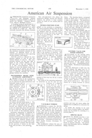
A PNEUMATIC Suspension system for rvg oods and passenger vehicles designed to promote stability is shown in patent No. 803,842. (General Motors Corp., Detroit, Michigan; U.S.A.) A levelling action %is performed by a pair of air hellows (1) at the rear. These are supplied with compressed air under the control of a valve (2). This continuouSly meaSures the distance between the chassis -frame and the axle and applies the necessary corrective pressure to the bellows. A delaying device in the control valve prevents it from operating during, transient road shocks.
Anti-roll control is effected by compressive bellows -(3 and 4) and two tension bellows (5 and 6). The compression bellows on the near side is piped to the tension bellows on 'the off side, also to the rear bellows (7). It is this cross-connection which is claimed to keep the chassis frame level when cornering by lifting one side and lowering the other.' The specification contains a diagram showing the various pipings between the members. , TRANSMISSION BRAKE WITH AUTOMATIC ADJUSTMENT
A BRAKE acting on the transmission 1-1 is shown in patent No. 803,596. It can be operated by both mechanical and hydraulic means and includes a device for automatic adjustment. (S. A. Andre Citroen, 117/167 Quai de Jaye!, Paris.)
The drawing shows the layout of the brake in its simplest form. A drum (1) has in its periphery a V-shaped groove in which a pair of friction blocks (2) can engage. The blocks are mounted on rockers, pivoted about points 3. The other ends of the blocks can be spread by a pair of hydraulic units (4). Alternatively, the rockers can be worked by a pair of caliper-like levers (5) operated by rod or cable (6). The lever ends press on the crowns of the hydraulic pistons.
Automatic adjustment is achieved by mounting the hydraulic cylinders in a cylindrical ratchet. The cylinders have external turned grooves of ratchet outline and these engage with the bore of a split ring which has similarly shaped teeth. The split ring acts as a pawl; and if the return movement is greater than the pitch of the grooves, it moves to the next notch and provides a new positionp
B34 This self-adjustment also affects the mechanical linkage, because the distance between the pistons is kept constant Within the limits of one ratchet pitch at all times.
PETROL-INJECTION PUMP• ONE of the problems in designing a petrol-injection pomp is that the fuel is not self-lubricating. This ,means that the plungers must be provided with i lubrication system that does not permit the oil to be diluted by the fuel, A pump designed to these requirements is Shown in patent No, 803,760. (G. Wick,. R. Wolf and K, Schroeder, 'Richterswill,
Switzerland.) • The drawing shows a section of one of the pumping units. In oper
ation, a snarl-cam (I) slowly retracts a plunger (2), but allows it to move to the right at the moment of injection. This occurs when the projection on the lever (3) drops over the edge (4). The actual pumping. unit is a separate member, shown generally at 5. . Quantitative regulation is given by varying the
position of the stop face (6) by a means not shown.
The whole of the operating mechanism is immersed in oil (7) and oil also functions as a push-rod in the space 8. As the pressure at this point is always higher than that in the pumping space, any leakage results in oil mixing with the petrol, a matter of little importance. It is impossible for any petrol to get into the oil. The pumping apparatus gives a rapid action for efficient atomization.
VALVE-SEAT INSERTS
ACCORDING to patent No. 801,581, tungsten-alloy valve seats can overheat and thus shorten the life of the valves. The reason for this overheating is the large area of seating exposed to combustion, and the poor thermal conductivity of the joint with the casting. The patent describes a dimensional change in the seating that is claimed to alleviate this disadvantage. (Thompson Products Inc., 23555 Euclid Avenue, Cleveland, 17, Ohio, U.S.A.)
The modification reduces the area of the seating that is exposed to combustion
flame. The drawing shows a proposed design in which only a narrow band (t) is open to the cylinder. The dimensions given specify that the overall diameter of the insert shall not exceed 1.1 times the maximum diameter of the valve 'seating and that its radial width shall not exceed .010 inch. Though not ideal these dimensions facilitate production.
The insert is of thin -walled type so that it can conform to the counterbore wall. This is said to make for more intimate contact, and therefore better heat conduction, dissipating any heat that , is conducted through the exposed surface.
A seating produced to this design is said to reduce the area exposed to combustion by 88% over conventional types.
CONTROL VALVE FOR POWER STEERING CTUATION of the steering servo Ct control valve through movement of the steering column is the subject of patent No. 800,813. A miniature differential gear is incorporated in the column, and movement of the planet carrier operates.the valve. (Fulminawerk Franz Muller, Mannheim-Friedrichsfeld, Germany.)
The unit illustrated is built into the steering .column, the upper part (1) of which carries the wheel; whilst the lower end (2) is connected to the steering box. The two parts are connected by bevel gearing, which meshes with a planet pinion (3) on a free carrier. When the column .is turned, the orbital movement of the carrier operates a fluid control
valve shown end-on 'towards The valve is biased by a spring towards its Central position and does not move unless the applied force is sufficient to overcome the spring.
To enable the steering to be used in the event of power failure, the planetcarrier can be locked by screwing in a pointed plug (5).
SPRUNG SEATS
PATENT No. 803,806 describes a seat for cross-conntry vehicles. It incorporates a spring which can be adjusted for resistance, and has a damping device to prevent rebound. The patent comes from Bremshey and Co., SolingenOhligs, Germany.