


Gear Changing by Fluid Pressure
Page 33
If you've noticed an error in this article please click here to report it so we can fix it.
Ingenious Bendix-Westinghouse Device by which Change-speed Gears are Selected and Engaged by Pneumatic or Hydraulic Means
DOWER control of the gearbox is no 1 new idea, but we doubt whether many of our readers are familiar with the details of the mechanism involved. Interest therefore attaches to a new sch em e for which the BendixWestinghouse Automotive Air Brake Co., Pittsburgh, U.S.A., is responsible, a full description of which appears in a recently published British Patent Specification (No. 540,098).
Here is an outline of its working. Power is provided by compressed air, but vacuum or oil under pressure may alternatively be employed; the term used in the specification is fluid pressure. Furthermore, the method is not limited, in its application, to gear changing.
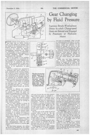
There is a control unit, operated by a miniature gear lever working in a gate, attached to the steering column. Air is fed to it from a reservoir and it also incorporates an atmosphere port. The valves are of the plunger type and are actuated by a camshaft which is capable of axial and rotary movement. , The pipes are numbered (4 referring to reverse) to show which is energized for each gear; e.g., pipe 1 conveys air for operating first gear, etc. Unnumbered pipes, shown broken off, are for lubrication.
Selection is effected by rotating part 13, coupled by rod 15 to a piston in cylinder 7, whilst the gears are shifted by moving part 13 axially, the rod on which it is mounted carrying a piston in cylinder 10. Both these cylinders (7 and 10) are double acting and both pistons, when not pneumatically energized, are held by springs in their midway positions.
One of these springs is shown in the drawing depicting cylinder 7 in section. From this view, how it works can be understood. The other spring is contained in cylinder 11 and functions similarly. Cylinder 10 operates quite normally, so no section drawing of it is included. In cylinder 11 a dash-pot device may also be incorporated for delaying gear shifting.
Clearly, it is of importance that selection must be completed before a gear is shifted into engagement, and that disengagement must be fully effected before selection of another gestr begins.
For the former purpose, two valves (8 and 9) are provided; for the latter, there is a locking gear (14) co-operating with part 13 and the rod (15) connecting it with the piston in cylinder 7.
When first speed is required, air is admitted to pipe 1, the other three, delivering from valve 12, being open to atmosphere. Pressure is thus created in cylinder 7, and part 13 turns so that its spring-loaded finger picks up the first-gear selector fork. 'From pipe 1, air also flows to valve 9, but goes no farther until cylinder 7 has completed its work.
The last part of the stroke of rod 15 actuates valves 9 and 8. By the former, air is admitted to pipe 5. By the latter, nothing is accomplished, because pipe 4 is open to atmosphere at the control end (12).
As a result of energizing pipe 5, pressure is created in cylinder 10 at the left-hand end and the selector fork for first gear is moved to the right.
To disengage first gear and to engage second, the lever is moved appropriately, pipe 1 is opened to atmosphere and pipe 2 is energized. Pipe 1 is still in communication with pipe 5, so pressure in cylinder 10 is released and the piston, under the influence of the spring in cylinder 11, moves to the neutral position disengaging first gear.
Until this action is completed, rod 15 is positively locked by mechanism 14. However, when part 13 regains its axially central position, plunger 14 drops off duplicated cam 16, falling into the recess shown, and releases rod 15.
While this has been happening, pipe 2—just energized—has been unable to supply air to cylinder 10, because the plunger of valve 8 has been held up by a cam (17) on rod 15, thus cutting off communication between pipes 2 and 6. So soon, however, as locking mechanism 14 frees rod 15, this too is returned by its spring to the midway position and thereby performs the double function of setting part 13 for engagement of second gear and establishing communication in valve 8 between pipes 2 and 6. As a result, the next action is the travel to the left of the piston in cylinder 10 and the engagement of the second speed.
For third gear, pipe 2 is opened to atmosphere, allowing air to escape—by the same route by which it entered— from the right side of the piston in cylinder 10, whilst pipe 3 is energized and feeds air through valve 9 and pipe 8 to the left side. Reverse is engaged by a method similar to that for first gear, except that pipe 4 is energized and cylinder 7 acts in the opposite direction, whilst valve 8 performs the functions formerly effected by valve 9.