PATENTS SUMMARIZED.
Page 22

If you've noticed an error in this article please click here to report it so we can fix it.
Two New Tractors.
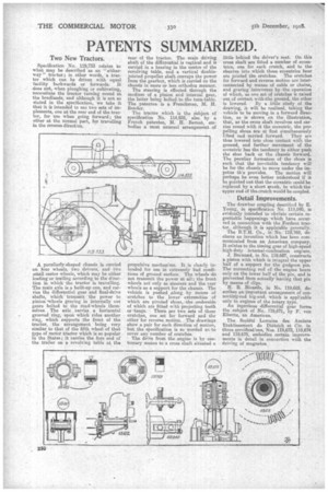
Specification No. 119,733 relates to what may be described as an " eitherway " tractor ; in other words, a tractor which can be driven with equal facility backwards or forwards. It does not, when ploughing or cultivating, necessitate the tractor turning round at the headlands, and although it is not so stated in the specification, we take it that, it is intended to US3 two sets of implements, one at the rear end of the tractor, for use when going forward; the other at the normal part, for travelling in the reverse. direction.
A peculiarly-shaped chassis is carried on four wheels, two drivers, and two small castor wheels, which may be either leading or trailing according to the direction in which the tractor is travelling. The main axle is a built-up one, and carries the differential gear and final-drive shafts, which transmit the power to pinion *wheels gearing in internally cut gears bolted to the road-wheels themselves. The axle carries a horizontal grooved ring, upon which rides another ring, which supports the front of the tractor, the arrangement being very similar to that of the fifth wheel of that type of motor tractor which is so popular in the States ; it carries the fore end of the trailer on a revolving table at the
rear of the tractor. The main driving shaft of the differential is vertical and is carried in a bearing in the centre of the revolving table, and a vertical doublejointed propeller shaft conveys the power from the gearbox, which is carried on the chassis in more or less orthodox manner.
The steering is effected through the medium of a pinion and internal gear, the latter being bolted to the turn-table. The patentee is a Frenchman, M. H. Bender.
Tho tractor which is the subject of specification No. 114,835, also by a French patentee, M. H. Bernat, ern, bodies a most unusual arrangement of propulsive rnechansm. It is clearly intended for use in extremely bad conditions of ground surface. The wheels do not transmit the power at all; the front wheels act only as steerers and the tear wheels as a support for the chassis. The vehicle is pushed along by means of crutches to the lower extremities of which are pivoted shoes, ,the underside of which are fitted with projecting teeth or •tangs. There, are two sets of these crutches, one set for forward and the other for reverse motion. The drawings show a pair for each direction of motion, but the specification is so worded as to cover any number of crutches.
The drive from the engine is by customary means to a cross shaft situated a little behind the driver's seat. On this cross shaft are fitted a number of eccentrics, one for each crutch, and to the sheaves into which these eccentrics bear arc jointed the crutches. The crutches for forward and reverse motion are interconnected by means of cable or chains, and gearing intervenes by the operation of which, as one sot of crutches is raised out of contact withithe ground, the other is lowered. By a little study of the drawing, it will be realized, taking the vehicle to be moving in a forward direction, as is shown on the illustration, that, as the cross shaft revolves and carries round with it the eccentric, the propelling shoes are at first simultaneously
lifted and carried forward. They are thus lowered into close contact with the ground, and further movement of the eccentric has the tendency to either push tho shoe back or the chassis forward. The peculiar formation of the shoes is such that the inevitable tendency will be for the chassis to move under the im
petus th's provides. The motion will perhaps be even better understood if it be pointed out that the eccentric could he replaced by a short crank, to which the • upper end of the crotch would be coupled.
Detail Improvements.
The drawbar coupling described by E. Young, in specification No. 119,840, is evidently intended 'to obviate certain regrettable happenings which have occurred in connection with the Fordson tractor, although it is applicable generally. The B.T.H. Co., in No. 119,769, declares an invention which has been communicated from an American company. It relates to the timing gear of high-speed high-duty internal-combustion engines.
J. Burnand, in No. 119,687, constructs a piston with which is integral the upper half of a support for the gudgeon pin. The connecting rod of the engme bears only on the lower half of the pin, and is prevented from actually leaving that pin by means of clips.
H. R. Ricardo, in No. 119,685, describes an important arrangement of connectidg-rod big-end, which is appl:cable only to engines of the rotary type. An ingenious differential gear forms the subject of Na.. 119,671, by F. von Elbertz, an -American.
The Societe Lorraine des Anciens Etablissenient de Dietrich et Cie. in three specificatFons, Nos. 119,672, 119,674. and 119,675, embodies certain improvements in detail in connection with the driving of magnetos.


