


A Compact New Air Servo
Page 61
If you've noticed an error in this article please click here to report it so we can fix it.
Clayton Dewandre Equipment Brought to Britain Has Particular Advantages for the Operation of Disc Brakes
AS announced briefly in last week's issue of The Commercial Motor, the Clayton Dewandre Co., Ltd.. have introduced a lightweight air-servo braking system making use of an Airpak servo. This type of servo has been available in the U.S.A. and on the Continent for a number of years. but this is the first time that it has been generally available for installation on British vehicles.
The introduction of this system is particularly important in view of the possibility of the general adoption of disc brakes in the near future. Such brake assemblies are likely to have to be hydraulically operated because of the difficulty of achieving sufficiently high pad pressures with direct air operation.
Another important consideration is that the S.C.4 new single-cylindered air compressor and the Airpak servo unit are readily interchangeable with Clayton Dewandre exhausters and Hydrovac suspended-vacuum servos.
Four Basic Components
The Airpak is a servo, not an airhydraulic actuator: therefore the brake pedal remains hydraulically linked to the wheel-brake units in the event of a failure in the air-pressure system. This is a big safety advantage compared with conventional air-hydraulic systems.
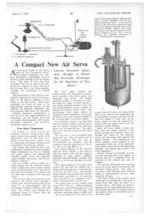
The Airpak unit comprises four basic components combined into one assembly. These components are the air cylinder and power piston, the hydraulically actuated control valve, the hydraulic output cylinder and piston, and the air pressure reservoir. , The air cylinder consists simply of a shell, welded into the reservoir section, which contains the power piston, piston return spring and push rod. One end of the push rod is bolted to the piston, and the other end is pinned to the hydraulic piston.
The pressure side of the piston is connected to the control valves through a control tube: the non-pressure side of the piston is in communication with the atmosphere through a drilling in the end plate. The control valve consists of a hydraulic piston in contact with the diaphragm assembly. The valve body contains the compressed-air and atmospheric poppetvalve assembly, valve-return spring and diaphragm bias spring. The poppet assembly includes a two-stage air valve, the small first stage of which permits a low initial hydraulic pressure from the brake-pedal-actuated master cylinder to operate the Airpak control valve. The second-stage valve opens during an emergency -brake application, when compressed air has to be admitted rapidly to the working side of the power piston.
The hydraulic cylinder is fed with fluid from the master cylinder and this passes into the chamber between the hydraulic piston and the push-rod seal. The outlet port in the end cap is piped to the wheel cylinders.
The reservoir is stove-enamelled both inside and out. There are three sizes of Airpak available, with 3-in., 4-in, or 4-4-in.-diameter air cylinders, and the respective reservoir capacities are 550 Cu. in., 520 Cu. in. and 880 cu. in.
The outside diameter of the reservoir with the 4f-in. cylinder is the same as with the smaller sizes. but the length is increased to give greater capacity. Optional hydraulic-output cylinder sizes of 1 in. or 1f-in.-bore diameter are available.
The single-cylindered air-cooled compressor for use with the Airpak has a flange mounting and gives a displacement of 4 c.f.m. at 1,250 r.p.m. The cylinderhead assembly incorporates the unloader mechanism controlled by the governor valve, and this is set to permit a maximum Working pressure of 105 p.s.i.
The safety valve on the cylinder head blows off at 150 p.s.i. When running at 1,000 r.p.m. and developing 105 p.s.i., the compressor absorbs only. 0.65 h.p. The maximum operating speed is 2.800 r.p.m.
So far as operation of the servo is con
cerncd, when the brakes are released both sides of the control-valve diaphragm are at atmospheric pressure, and this condition also applies to both sides of the power piston, .so that the piston-return spring holds the piston away from the hydraulic output cylinder.
When the brake pedal is depressed, fluid from the master cylinder is displaced through the hydraulic inlet port, through the centre of the hydraulic piston, past the check valve and into the output cylinder. The resistance at the wheel cylinders causes pressure to be transmitted to the rear of the hydraulicvalve piston which moves the diaphragm assembly and isolates the control tube from atmosphere.
Further increase in hydraulic pressure lifts the first-stage inlet valve against air pressure and air is admitted from the reservoir to the control tube and air cylinder.
The pressure differential thus resulting moves the power piston and operates the hydraulic output piston. This stage is the power crack-off point and normally occurs at approximately 40 p.s.i. input hydraulic pressure.
The force acting on the control valve diaphragm is in proportion to the powerpiston force and takes the form of a reaction force. This force is, however, balanced by the input hydraulic pressure. Thus pedal sensitivity is retained because the reaction force is transmitted back to the brake pedal.